Have you ever considered the number of moving parts in the engine of your car? A standard 4-cylinder automobile engine has maybe 200 individual components. Most of these components reciprocate and rotate in unison at 4,000 rpm.
Eight of these 200 components are assembled together as the radiator water pump. This water pump recirculates cooling water through the engine and the radiator. This pump is a pulley driven, variable-speed centrifugal pump with a volute, impeller, shaft, bearings, a mechanical seal and other secondary seals (gaskets, O-rings, V-rings, grommets, etc.).
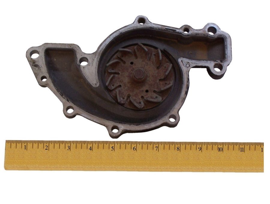 The radiator water pump is similar to any water pump you might encounter in industry, with some noteworthy differences. Your car’s radiator water pump:
1. Can handle slurry (entrained solids, rust, slag, silica, mineral scale, asbestos).
2. Can withstand temperature changes from freezing to boiling in a few moments.
3. Is a variable speed pump, a function of the engine rpm and your foot on the accelerator pedal.
4. Can handle variable operating time, 5 minutes to the grocery store, or 24-hours a day on a family vacation.
5. Can withstand extreme vibrations. Each revolution of the internal combustion engine is composed of 4, 6 or 8 explosions
6. Is a portable pump mounted on the engine block, not on a solid, level, grouted, epoxy-cement foundation.
7. Is not a precision machined pump. Most parts are stamped, cast or extruded.
8. Is not precision aligned. The shaft is powered by a slapping, tensioned, radial- loaded v-belt slipping and squealing between two pulley wheels.
9. Carries a cheap shaft seal with no environmental control or ‘Seal Plan’.
10. Carries a cheap bearing (a sleeve bushing) lubricated with the dirty, hot radiator water, no oil or grease.
And most important, your car’s radiator water pump can operate for 18 or 20-years under these adverse conditions without premature failure or mysterious leakage. Wouldn’t it be nice if industrial pumps could withstand these conditions for 2 decades?
As a machine, the industrial pump is a relatively simple device. Pumps are only slightly more sophisticated than a soup spoon. You see, a pump has one moving component, the shaft assembly. A soup spoon has no moving components. Any force or abuse that might damage a soup spoon would originate from an external source outside the spoon.
There is little to break on an industrial pump. The shaft never breaks into 7 pieces. The sleeve doesn’t break. The impeller never splits into 5 pieces. The components that cause the most headaches, the seal and bearings, aren’t parts manufactured by the pump company. Most seals and bearings are contracted by 2nd and 3rd party assemblers. And like the spoon, most pump problems originate outside the pump.
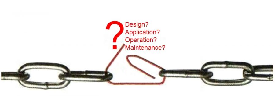
Reliable pumps result from proper design, proper application, proper operation and proper maintenance. These four elements (design, application, operation and maintenance) form the reliability chain. A chain is only as strong as its weakest link. If one or more of these four elements are inadequate, incorrect or missing, the reliability chain is weak.
 Reliability Begins with Instrumentation
A well-cooked meal begins with instrumentation. You need a thermometer and a timer clock just to warm a store-bought pizza in the oven. The instrumentation panel (the dashboard) of every car stares the driver in the face. Look into the cockpit of an airplane, or passenger jet. Pilots (operators) fly (control) the airplane with instrumentation.
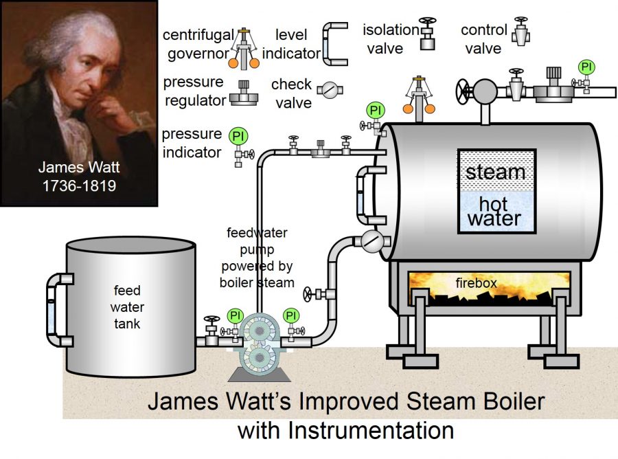
Industrial Instrumentation is about 250 years old. James Watt (1736-1819) is history’s best known Instrumentation Technician. James put the word ‘Horsepower’ into the dictionary. He held patents on the mechanical centrifugal governor, the pressure regulator and the rotary steam engine. James incorporated instrumentation to develop the modern steam boiler that accelerated the industrial revolution.
 A process engineer might want to know the liquid velocity, or the pressure in a pipe. A pump generated that velocity and pressure. Instrumentation measures the velocity and reports the pressure. Production engineers always want to know the flow volume through the pipes and the elevation (level) in the vessels. Pumps develop the flow and fill the vessels. Instrumentation measures the flow and reports the level in a vessel.
Chemical process pumps consume a large part of the daily maintenance budget. This is because too many pumps are operated without adequate instrumentation, and rarely are the operators taught to interpret the information on the gauges.
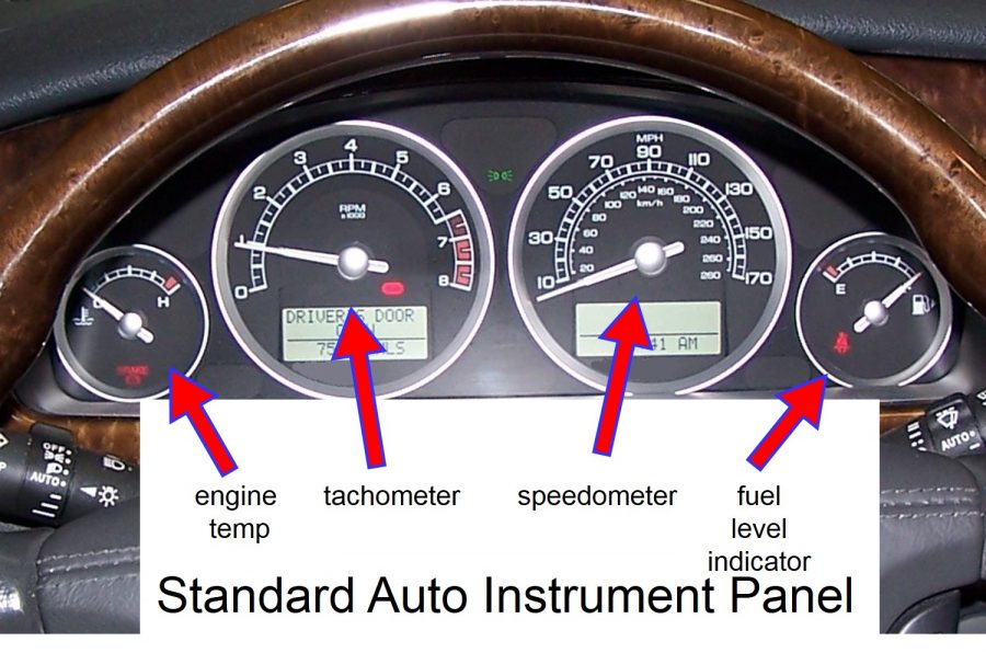
The dashboard of a simple, stripped-down inexpensive car will show the driver a speedometer, a tachometer (engine rpm), an engine temperature gauge and a fuel level indicator. The driver (the operator) makes decisions based on the information provided.
 Likewise, a pump operator needs certain information about a pump to control the pump. The process engineer needs this same information to improve the yield or accelerate a reaction. And, the reliability engineer needs the same information to modify and improve reliability.
The Pump Curve is a graph of the pump’s performance profile. The curve is easy to understand. It indicates that the pump will discharge a certain volume of a liquid, at a certain differential pressure, at an indicated speed, while consuming a specific quantity of power (horsepower or kilowatts). Variable speed performance curves are published for variable speed pumps.
Let’s say that a ‘cold water’ application requires 800 gallons per minute (gpm) of flow to meet a production schedule. The pipe system for this ‘cold water’ application contains (or requires) 92-units of energy, called 92-ft of head. The design engineer selects a pump designed to develop 92-feet of best efficiency head, at 800 gpm. (I will refer to this application a few times in this article.)
Flow Meter
For reliability and improved MTBF stats, this pump needs to operate as close as possible to 92-ft @ 800-gpm. A flow meter will report the 800-gpm. Suction and discharge pressure gauges will report the 92-ft of differential head across the pump. The pump loses efficiency as the duty coordinates migrate away from the design coordinates. A quick look at the pump performance curve will show the efficiency decline as flow and head vary.
What happens as a pump strays from the design coordinates and there is no instrumentation to interpret? The pump will vibrate. The pump will overheat. The pump will make excess noise. The pump can overload the motor. The pump can suffer cavitation. Strict tolerance components in relative motion inside the pump can rub, scrape and bind. Basically, unplanned maintenance happens without instrumentation. And the pump (the asset) produces no revenue while disassembled on a table in the repair shop.
Suction and Discharge pressure gauges (or transducers) are necessary to determine the pump’s health. The tendency in a consuming society is to produce more. Most companies want to increase revenue next year compared to this year. The dairy wants to sell more milk. The petroleum company wants to sell more gasoline. The employees want to earn more next year. In the chemical process industry, it means pumping an ever-increasing volume of product.
Certain chemical process applications require a steady or even increasing head as flow rises. The relationship between head and flow in a pump is such that head tends to drop as flow rises. This can cause problems. To navigate these potential problems, a process pump needs suction and discharge pressure gauges.
Pressure Gauges
In the example offered in this article, the pipe system with the cold-water pump requires 92-feet of head. Feet of head converts easily into pressure. For cold water, 92 feet of head is 40-psi of differential pressure. You can learn more about head and pressure in another Pump Guy article published by Empowering Pumps.
What does 40-psi of differential pressure mean? It means:
- If the suction pressure is in a vacuum with a gauge (or transducer) reading 10-inches of Mercury (10-in. Hg), the discharge gauge should read 35-psig. The differential pressure across the pump would be 40-psi.
- If the suction pressure indicator reads 0-psig, the discharge gauge should read 40-psig (40-psi differential).
- If the suction pressure is 5-psig, the discharge gauge should read 45-psig (40-psi differential).
- If the suction gauge reads 12-psig, the discharge pressure gauge should read about 52-psig (40-psi differential).
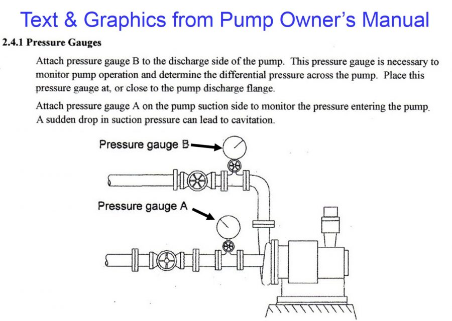
You see from these examples the discharge pressure gauge reading is a function of the suction pressure gauge reading. The suction pressure is the pump’s reference point. For this reason, the Owner’s Manual of many pump companies specify suction and discharge gauges.
 The pump receives suction pressure (reported on the suction pressure gauge). The pump (and motor) add more pressure (energy). (This is the information you see on the performance curve.) The suction pressure plus the pressure added by the pump and motor, is the discharge pressure (reported on the discharge pressure gauge).
The suction pressure reading is the most important pressure in the pump for a few reasons:
- The pump’s work begins at suction pressure (whether vacuum or a pressure above atmospheric pressure).
- The pump requires a certain amount of suction energy (head, pressure) in the liquid to perform correctly. This is called the NPSHr. The NPSHr appears on most pump curves and increases with the flow. The suction pressure reading lets the operator know that this required suction energy arrives into the pump.
- The suction pressure gauge reading must include a margin of energy over and above the pump’s requirements. This margin is called the NPSHa.
The engineer and operator know this water pump is at its optimum design point when the pressure differential is 40-psi. As the differential pressures rise above, or fall below 40 psi (observed on the gauges), the maintenance will rise on this pump.
I am fortunate to visit many process plants around the globe. My experience indicates that too many process pumps lack adequate instrumentation.
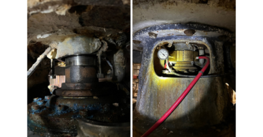
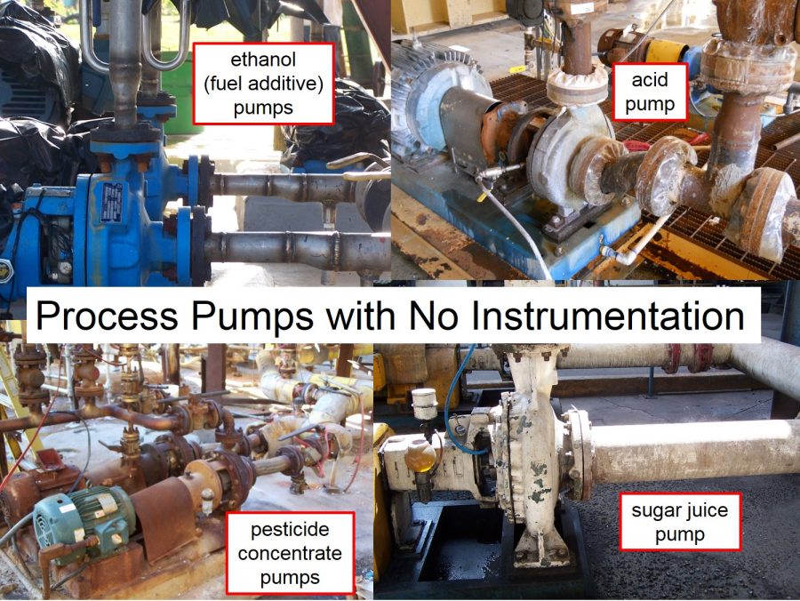 I see many pumps with no instrumentation. I see some pumps with a pressure gauge (or transducer) mounted onto the discharge nozzle of the pump. However, I see very few pumps with a pressure indicator at the suction nozzle, and discharge nozzle. I challenge you. Walk out into your production area and look at the process pumps.
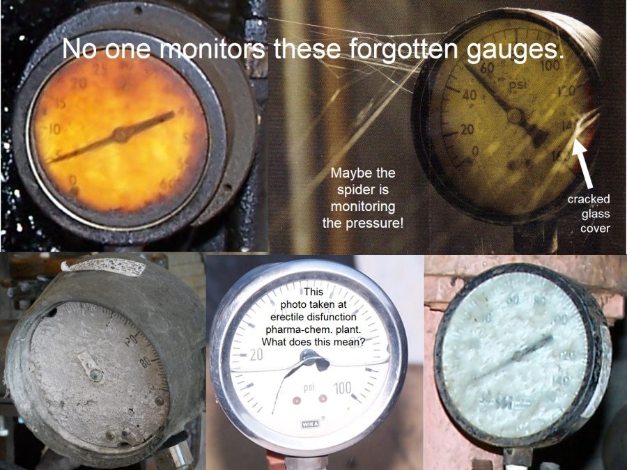
Frequently, I see pressure gauges where the needle has fallen off the stem. I see pressure gauges that no one can read or interpret. I see gauges where the cover glass is fogged…or broken. And, this is a shame because no one is interpreting the gauge, or taking action to resolve cavitation or undetermined vibrations.
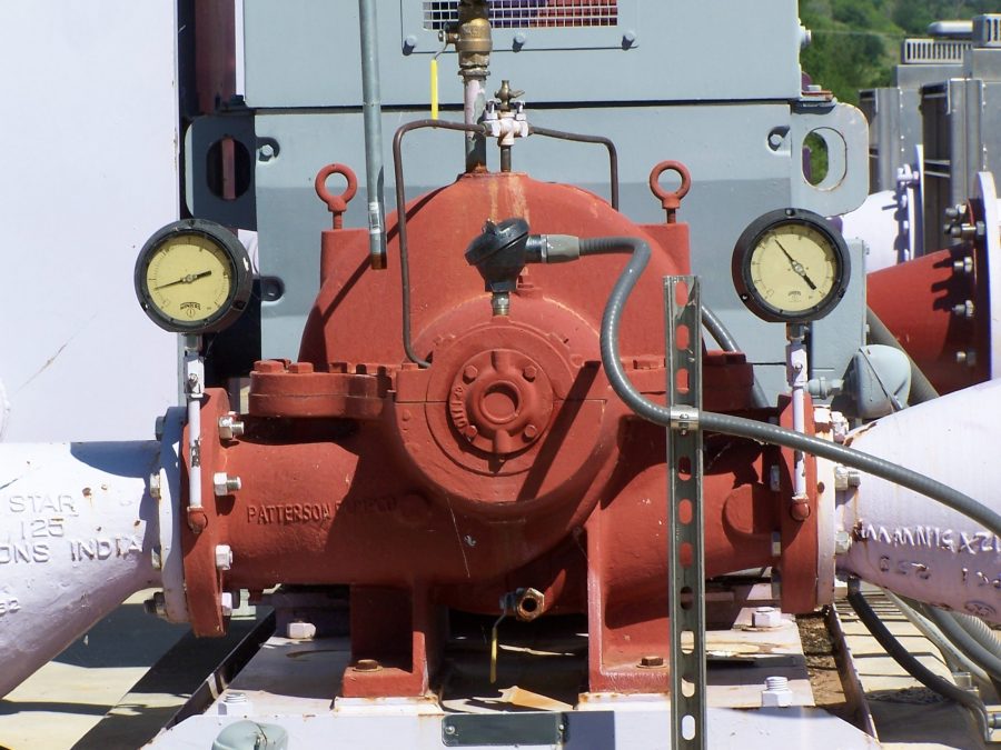
 All pumps should have suction and discharge pressure gauges (or transducers) installed. The gauges should be functioning, clean, calibrated and thermally and chemically compatible with the liquid and equipment metallurgy. Someone should train the operators to interpret the information on the gauges.
 Operators should actively monitor the differential pressure. The pump is sick if the differential pressure is too high…or too low. The pump will vibrate waste energy, overheat, stress the seal and bearings, suffer cavitation, and become a maintenance headache. And this ain’t rocket science!
The engineering professor in the university repeats many times, “Pumps develop differential head.” “Pumps pump differential pressure.” A graduated engineer takes a position with responsibility in a refinery or chemical plant. And, the engineer doesn’t order to install pressure gauges on the suction and discharge nozzles of the process pumps in his area.
Later, the engineer perceives he has a vibration problem, or a cavitation problem, or a mechanical seal problem. How can so many intelligent, well-educated people get it so wrong?
Some would blame the instrumentation tech for not installing instrumentation. But the instrumentation tech takes instructions and leadership from the engineer. If the engineer doesn’t order instrumentation for his pumps, the instrumentation tech will stay in his office and read an article on instrument precision, or accuracy, or drift.
Some would blame the pump manufacturer for not installing gauges on a new pump. The pump manufacturer isn’t inspired to install gauges on a new pump. The gauges will increase his sale price. Purchasing won’t pay for anything that wasn’t specified. And besides, the pump business isn’t really about selling new pumps. It really is more about selling pump parts. The pump company sells a pump for an application once every 20 years. For the next 20-years, the pump company earns much more money by selling spare parts for that pump. Why decrease the earnings with information to improve reliability? DUH!!!
Do the Basics First
It is fashionable these days for the reliability department to invest over a million dollars in hardware (vibration analyzers, laser aligners, thermo-graphic cameras, synthetic lubricants, ultrasound, borescopes, etc.) and computer programs (RCM, CMMS, Six- Sigma, Total-Quality, etc.) to improve the reliability of rotating equipment. Many people hope and pray that these devices will show them the way to reliable pumps.
These devices and tools are definitely useful, but frequently employed ‘out of sequence’. What do I mean by ‘out of sequence’?
A child must learn to walk before the child can run. A student must dominate basic math before tackling trigonometry or calculus. If the teacher forces calculus onto a student before the student can add and subtract, that would be ‘out of sequence’. Likewise, it is illogical to assume that some digital, battery-powered device will miraculously bounce your reliability stats from 30-months MTBF to 12 years on your process pumps. It ain’t gonna happen, People!
I would use instrumentation (gauges, flow meters, etc.), performance curves and training to foster and improve the reliability (MTBF stats) to about 100 months (9-years) in a population of pumps. Then, I would slowly introduce the newer technology devices to stretch the reliability stats to 10, 12 or more years.
You must know how to ride a bicycle before trying to ride a motorcycle. How is a motorcycle going to help you if you can’t even balance yourself on a bicycle? The motorcycle will only multiply your problems. Does this make sense?
I always spend time covering these points in my lectures. Instrumentation technicians and trained operators are vital to all reliability programs.
The Pump Guy is Larry Bachus, a maintenance practitioner, inventor, author and retired member of ASME based in Nashville, TN. You can contact Larry at: larry@bachusinc.com or call 615-361-7295.