Author: Randal Ferman
A word on the terminology: Net Positive Suction Head (NPSH) is the sum of the total static plus kinetic pressure minus the liquid vapor pressure, at the pump suction nozzle or impeller entry, expressed in terms of ‘head.’ Confusion may occur if one does not know that there are two basic NPSH parameters to consider. One is the NPSH of the system, and this is commonly referred to as NPSH Available or NPSHA. The other is the NPSH Required by the pump, or NPSHR.

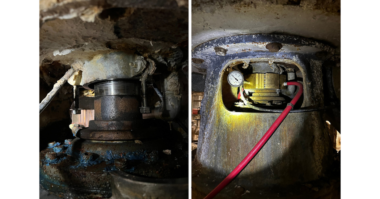
Figure 1. Component Parts of NPSHa
Figure 1 above illustrates the component factors of NPSHA. In this chart, atmospheric pressure is dominant but in other systems the other factors may have relatively greater or lesser importance. In a system open to atmosphere, the liquid surface elevation above or below the first stage impeller and estimated intake friction losses may be used in lieu of a pressure reading at the pump intake. Convert pressures readings to head, in units of meters or feet, by dividing by the specific weight. Pump texts, and other publications show how and where the readings are taken and how to perform the calculations.
Determining NPSHR requires testing the pump over a series of carefully controlled flow and suction conditions in a laboratory or factory test facility. For some pump types, such as larger size open pit vertical pumps, a full scale unit NPSHR test is very often not practical. Scale model pump testing may be the most practical means of obtaining the NPSHR data. The accepted industry standard is that, at a given rate of flow, NPSHR represents the level at which 3% degradation in pump total head occurs at the first stage impeller. The NPSHR characteristic curve representing 3% head drop is also known as ‘NPSH3.’ Some manufacturers publish their NPSHR curves, or portions thereof, with margin above NPSH3.
A typical set of pump performance curves at a fixed operating speed, including NPSHR versus rate of flow, are shown in Figure 2 below.
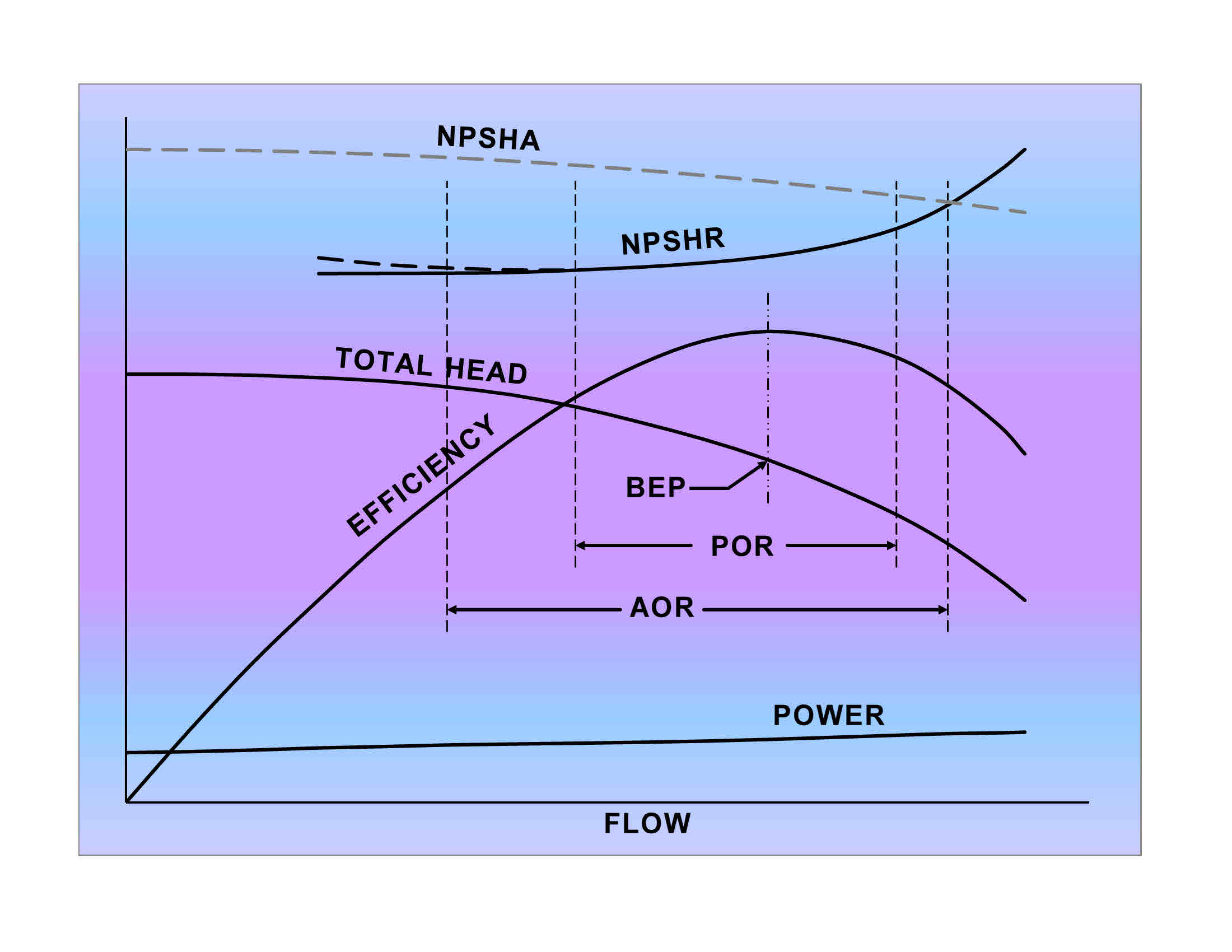
Figure 2. Pump performance characteristics
Some additional information on the chart is shown for reference, including a curve of NPSHA, the preferred operating range (POR), the allowable operation range (AOR), and identification of the best efficiency point (BEP) flow.
A few characteristics of the NPSHR curve deserve mention. At its left side the curve begins not at zero, but at some intermediate flow. This intermediate flow may be the lowest flow for which a reference pump was tested, below which the pump experienced heavy internal recirculation and elevated levels of vibration. The low flow end of the NPSHR curve may, in fact, represent the pump’s minimum continuous flow. Then from left to right, the curve continues with a mostly shallow rise characteristic, or sometimes dipping, and then rising gradually towards Best Efficiency Point (BEP) flow. Beyond BEP flow the NPSHR curve climbs steeply. The high NPSHR often effectively limits the pump’s maximum flow capability.
It is important to understand how the system’s NPSHA varies across the range of pump operation. This may influence the pump selection, the intake piping and the necessary NPSH Margin. Intake friction losses vary with the rate of flow, and can be significant with long lengths of piping and a number of fittings. Changes in overall system pressure or changes in the liquid elevation above the pump intake impeller directly add or subtract from the NPSHA. A curve of the system NPSHA as shown at the top of Figure 2, can be determined by the process engineer. For a vertically suspended pump placed in an open tank or sump, the minimum NPSHA is determined by the minimum submergence of the pump’s intake impeller. In such an arrangement, the NPSHA can normally be assumed constant for a given submergence and at any rate of flow.
It is important to understand uncertainties in the system resistance and process head requirements as a function of flow, including allowance for the as-built conditions. The pump’s rated head-flow point will normally have a unilateral ‘plus’ tolerance. The operating point or operating range of a rotodynamic (centrifugal/mixed flow/axial flow impeller) pump will be determined by the intersection of the system characteristic curve and the pump head-flow curve.
In the range of flow greater than the pump’s Best Efficiency Point (BEP), NPSHR rises. Of particular interest is the intersection of the NPSHA and NPSHR curves which defines the highest rate of flow for which the pump can safely operate. As the rate of flow increases, NPSHR climbs steeply and may quickly exceed the NPSHA. This condition is to be avoided. At the very least, the pump will lose head and fall short on hydraulic performance demand. Vibration levels increase. Significant cavitation and erosion damage may result. In some instances, cavitation can lead to system instability and severe hydraulic transients (water hammer). Insufficient NPSHA may cause the pumped liquid to flash into vapor causing loss of prime. Inside the pump, close running clearances may run dry and catastrophic damage is a real possibility.
How do we define ‘NPSH Margin’? There are two ways. One way is to express NPSH Margin as the ratio of [NPSHA divided by NPSHR]. Another way is to express NPSH Margin in absolute terms as the difference of [NPSHA minus NPSHR]. For instance, an NPSH Margin ratio of 1.1 indicates the NPSHA is 10% above the NPSHR. Alternatively, say the value of NPSHR at a given rate of flow is 10 meters and the NPSH Margin is 1 meter. These two example expressions of NPSH Margin are equivalent. Both ways of expressing NPSH Margin are used in practice, although for higher energy pumps where the value NPSHR may be high, an NPSH Margin ratio is more commonly used.
A margin ratio of 1.0 means there is sufficient NPSHA for operation of the pump, but in theory, there is zero margin. In practice, even with ‘zero margin,’ the suction impeller may actually have margin. With a vertical condensate pump in a suction barrel, for instance, it is common practice to specify 0.0 NPSHA at the suction nozzle. The liquid height in the barrel provides a static head of NPSHA to the pump intake impeller. Also, the zero margin condition would be specified for the highest expected rate of flow – a condition that may or may not ever be seen in actual operation. At rates of flow less than the maximum, the NPSHR will be lower and the NPSH Margin will exceed 1.0.
In hydrocarbon applications, the cavitation behavior is not so abrupt and unforgiving compared with that of cold water. With decreasing suction pressure the pump loses performance more gradually and even when the NPSH margin ratio drops below a value of 1.0, the pump may still operate satisfactorily. The standard API 610 / ISO 13709 Centrifugal Pumps for Petroleum, Petrochemical and Natural Gas Industries disallows a hydrocarbon correction which would otherwise reduce the NPSHR, for shop NPSH tests on water. This, in effect, provides NSPH margin.
What are the factors that can affect NPSH Margin? To preface an answer to this, there are issues inherent in the design and selection of the pump itself, and then there are issues that relate to the properties of the fluid being pumped and to the operation of the pump.
The impeller material, in addition to its compatibility with the pumped liquid properties, must be appropriate for the velocity of flow. An index for this is the peripheral tip speed (velocity) at the impeller eye, and in terms of the potential for cavitation erosion damage, the impeller tip speed, coupled with liquid density, are primary factors.
The impeller vane design at the inlet may also factor into NPSH Margin. Impellers with a high level of suction performance capability are sensitive, from the standpoint of cavitation and vibration, to operation at off-BEP flow conditions. The key parameter for pump suction performance is Suction Specific Speed, S (NSS). Values of S > 210 metric (NSS > 11,000 in U.S. customary units) may require closer attention to pump operating range, depending upon size of the pump, its speed and other design and application factors.
What level of NPSH margin should be specified? There are numerous variables that enter in and there is no one-size-fits-all answer to this. Traditionally manufacturers, engineering firms and consultants specify NPSH Margin recommendations, often based on sound experience. As one might expect, NPSH Margin values for a given application based on information provided by different sources is not always consistent.
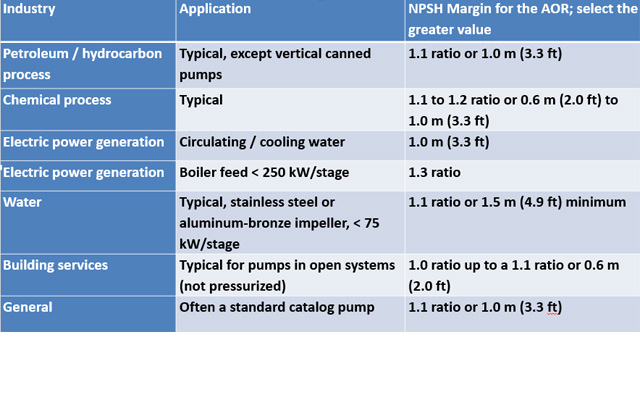
The Hydraulic Institute’s publication ANSI/HI 9.6.1-2012 Guideline for NPSH Margin provides specific values and margin ratios, for common pump application categories. Table A (below) provides selected values from this guideline applicable to the pump’s Allowable Operating Range (AOR). The HI guideline provides NPSH Margin recommendations for other industries and application categories, as well as additional values for the Preferred Operating Range (POR), in the range closer to the BEP flow. It should be noted that the values provided in the HI publication are not normative and the use of other margin values may be justified.
Is there a benefit to specifying a greater NPSH Margin? Maybe ‘yes,’ and quite possibly ‘no.’ It depends primarily upon two separate issues. One – do the uncertainties in the pump system characteristics, interactions and other unknowns warrant a greater NPSH Margin? Or two – does adding to the NPSH Margin improve pump performance and/or reliability? To increase the NPSH Margin either additional NPSHA must be designed into system or a pump with a lower NPSHR must be selected.
Building in additional NPSHA into a system may require larger piping to reduce intake friction losses, elevating tank or pressure vessel liquid levels or placing pumps at a lower elevation setting. These design measures add to the capital cost of the system.
Selecting a pump with a higher level of suction performance might possibly lead to operational compromises. The pump with a higher value of S (NSS) will almost certainly have a narrower window of operation with respect to acceptable vibration levels, seal and bearing longevity, and impeller cavitation erosion life.
Alternatively, lower NPSHR could be achieved by selecting a pump with a slower rotational speed. This pump option will cost more, but it may be a lot less expensive than attempting to alter the intake piping design.
Otherwise, an incremental increase of the NPSH Margin, especially if there is already an NPSH Margin ratio greater than 1.0 at the normal operating conditions, will probably not measurably improve pump performance or reliability. Typical NPSH Margin ratios are in the range of 1.0 to 1.3; a few are greater than this. But to fully suppress cavitation may require an NPSH Margin ratio of 4.0 or higher depending on the operating flow range. For most applications, this is simply not practical.
Table A. Selected NPSH Margins from ANSI/HI 9.6.1-2012 Guideline for NPSH Margin
| Industry | Application | NPSH Margin for the AOR; select the greater value |
| Petroleum / hydrocarbon process | Typical, except vertical canned pumps | 1.1 ratio or 1.0 m (3.3 ft) |
| Chemical process | Typical | 1.1 to 1.2 ratio or 0.6 m (2.0 ft) to 1.0 m (3.3 ft) |
| Electric power generation | Circulating / cooling water | 1.0 m (3.3 ft) |
| Electric power generation | Boiler feed < 250 kW/stage | 1.3 ratio |
| Water | Typical, stainless steel or aluminum-bronze impeller, < 75 kW/stage | 1.1 ratio or 1.5 m (4.9 ft) minimum |
| Building services | Typical for pumps in open systems (not pressurized) | 1.0 ratio up to a 1.1 ratio or 0.6 m (2.0 ft) |
| General | Often a standard catalog pump | 1.1 ratio or 1.0 m (3.3 ft) |
Certain applications such as high pressure water injection pumps, pipeline pumps, nuclear service pumps, high suction performance, large custom engineered pumps and high energy designs are beyond the HI document’s scope and require individual attention.
Does the appropriate NPSH Margin eliminate cavitation? An NPSH Margin ratio of 2 to 10 – often greater than a ratio of 4 – would be required to suppress all cavitation. It depends mainly upon the inlet geometry of the pump and the range of operation. For most applications, the pump will tolerate some cavitation without compromising reliability. For most applications it is impractical and unnecessary to completely suppress all cavitation.
NPSH Margin can only be determined by understanding the performance of both the pump and system. An appropriate NPSH Margin will allow the pump to operate over the range of flows required by the process, will keep the pump from cavitating excessively or losing suction prime and it should not add excessively to the capital cost of the system.
For an independent evaluation of the NPSH Margin for your pumping system, contact an experienced consulting engineer who can help with your specific application.