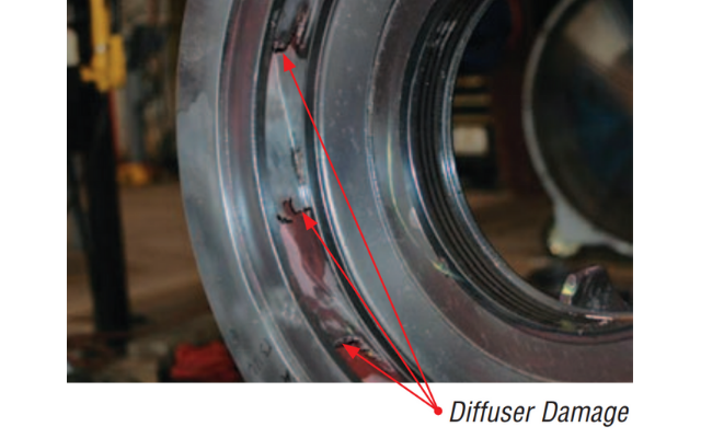
A coal fired power plant in the U.S. sought to reduce extensive wear to the first and second stage diffusers of its boiler feed water pumps. Excessive cavitation and wear damage was discovered during the 1989 and 1995 pump repair cycles. To mitigate the damage, significant modifications were made to the diffusers in 1997. The operating speed and conditions of service of the pump were also increased at this time. Inspections performed in 2005 and 2010, however, revealed the wear and cavitation continued. Station operators turned to Flowserve to determine the root cause of the damage.
After performing comprehensive onsite testing on the feed water system, Flowserve engineers found the pumps were being operated below BEP and that flow instabilities were the root cause of the cavitation and wear. Flowserve engineers designed modifications for the diffusers that would decrease the fluid velocity in the diffuser passage inlet areas and make the incident flow angles more preferential. They also recommended the feed pumps be operated at or near BEP.
A coal fired power plant located in Texas was experiencing recurring cavitation and extensive wear to the first and second stage diffusers of the two steam turbine driven multistage, double-case, boiler feed water pumps in Unit 1. The problem had been troubling station operators since 1989. A March 2010 inspection revealed extensive diffuser damage, prompting plant operators to commission Flowserve for additional onsite testing and a root cause analysis.
Background
In 1997, the following significant modifications were made to the pumps’ diffusers in an attempt to correct the problem:
• Diffusers were modified to a fully shrouded design.
• The “B-gap” of intermediate diffusers was increased from 1.7% to 3.4%.
• The “B-gap” of the suction diffusers was increased from 1.9% to 3.3%.
• A bias wedge was added to the diffuser guide vanes.
• The vane count of all diffusers was increased from 9 to 10.
To support increased operating speed and conditions of service, the double-suction first-stage impeller was also modified to accept the lower suction pressure. Tests conducted at full load and all scenarios revealed the NPSHA exceeded NPSHR by a sufficient margin.
Inspections in 2005 and 2010 showed the cavitation and excessive wear continued despite the 1997 modifications.
Testing
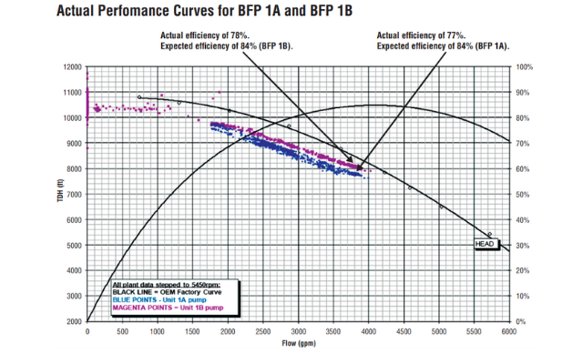
With the assistance of plant personnel, Flowserve engineers performed extensive onsite testing and analysis in 2010. Ultrasonic flow instrumentation and IPS Wireless™ sensors were installed at several key monitoring points to capture flow and pressure data respectively, and the data was transmitted to a central receiver. Plant DCS system provided temperatures and turbine speed data. Redundant pressure and flow data from the plant’s DCS was compared to test data for validation purposes. Testing showed the pumps were operating approximately 8% below BEP.
 Recommendations
After reviewing the collected data and performing a root cause analysis, Flowserve engineers determined the cavitation and wear were caused by flow instabilities compounded by operating the pump below BEP. When operated at flows below BEP, high specific speed pumps such as these can develop mismatched angles of incidence between the flow and the diffuser blade tips. In this case, the poor angles of incidence were creating local areas of pressure drop and recirculation within diffuser passageways, resulting in cavitation and wear.
To correct these conditions, Flowserve recommended making the following modifications and operational changes:
• Increase the “B-gap” between the impeller blade tips and the vanes of the first and second stage diffusers from 3.4% to 6.5%.
• Remove the bias wedges that were added in 1997.
• Operate the pumps at or near BEP, whether by changing the operating parameters or by implementing rerates.