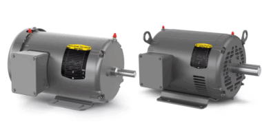
Vertically-oriented pumps are used primarily in municipal water, HVAC, and power plant operations, although it is not uncommon to see small vertical pumps in many industrial applications. Many vertical pumps utilize a flexible coupling to transfer power from the motor to the pump, so proper shaft alignment is an important part of overall machine reliability.
Reasons for Alignment
In most cases, the vertical motor is mounted to a NEMA C-face adaptor. This means that instead of using traditional motor feet, the drive end of the motor bolts axially to a adaptor plate, which bolts to the top (drive end) of the pump. The motor flange and adapter flange utilize a grooved joint (rabbet joint) to assure a precise fit.
But it is a common misconception that these types of machines to not need to be aligned. While the grooved joint may indeed minimize the possibility of offset misalignment, it does little to nothing to prevent angular misalignment.
The main causes of misalignment on vertical pumps are:
- machining errors
- trash or other contaminants between the motor and adapter flanges
Coupling Types
Typically, there are two types of couplings used in vertical pump applications – rigid and flexible. Rigid couplings of use a threaded coupling to “thread” the two shafts together, or a rigid bolted coupling. There are several different types of flexible couplings that can be used on vertical pumps.
One critical aspect of vertical pump couplings is that the coupling is often used to set proper impeller clearance, or lift, in the pump. When the pump is initially installed, the pump impeller rests on the pump casing. A gap is set between the coupling flanges. As the two coupling flanges are bolted together, the pump shaft and impeller are “lifted” off the pump case, setting the proper impeller to flange clearance.
Alignment Methods
Threaded couplings which connect the motor and pump shafts are aligned using a dial indicator and bracket. The indicator bracket is mounted to the motor shaft, and the dial indicator is zeroed on the inside of the C-face adapter. As the shaft is rotated, the indicator reads off the inside of the adapter. This method does not truly align the shaft centerlines. Instead it centers the motor shaft to the adapter. As long as the adapter is properly machined, and the measured surface is concentric to the pump, this would yield a relatively good alignment.
On bolted rigid couplings, traditional tools such as lasers or dial indicators, can be used to align the shaft centerlines. Normally the coupling bolts should be loosened when measurements are taken, so that the movement of the bolts within the coupling hubs allows the two machine shafts to rotate with a minimum of influence from the bolted connection. However, it is important to not loosen the bolts to the point that the impeller is dragging on the pump housing.
Aligning a C-face Motor
The main difference in aligning a vertical C-face pump and traditional alignment is this. Since the motor uses a C-face flange, the motor is bolting axially into the flange. There are no motor feet, per se. So to position the motor for proper shaft alignment, these two methods must be utilized.
Offset Alignment – Since most C-face flanges mount using a grooved joint, offset misalignment is typically small. But some motors can have C-face mounting, but not a locating groove. If parallel moves must be made, they are typically done using jacking bolts, which are mounted to the flange.
Angular Alignment – In this case, the bolts which bolt the motor onto the C-face flange become the “feet”. Shims can be added between the motor and than flange to make angular corrections to the alignment.


