In Part 3, we review the true differentiators between Two and Three Level Active Front End Drives and provide an overview of the relationship of AFEs and Noise Voltages
Authors: Garrett Abbott-Frey, US Process Drive Offer Manager – Industry Business, Schneider Electric, and Jack Creamer, Market Segment Manager, Pumping Equipment – Industry Business, Schneider Electric
When studying either a Water Treatment Plant or the mechanical systems of upstream Oil and Gas Artificial Lift Systems, a common question regarding drives and specifically Active Front End drives arises – “How do these solutions affect motor life and longevity?” Typically, the electric motors are costly elements in these applications, and upon failure results in long down times. Schneider Electric 3-level Active Front End drives add Common Mode suppression to typical levels as seen by tried and true 6 pulse input bridges. This CM Suppression results in better motor performance and improved bearing life.
Noise Voltages
Schneider Electric’s low harmonic drive solution achieves much lower harmonic input current distortion compared to passive diode bridges and previous generation two-level AFE drive solutions. The total harmonic distortion (THD i) of input currents is below 5%. Due to the switching actions of the active converter bridge to shape the input current, the drive generates noise voltages at switching frequency. These emissions are attenuated by an input LCL filter to values below 0.5%, as discussed in the preceding LCL filter design section. This minimizes any harmful impact on adjacent EMI/RFI-sensitive equipment.
In Figure 1, simulated voltage waveforms of Schneider Electric’s low harmonic drive are shown together with their averaged low-frequency components (averaged over one switching period). Three voltage levels form the phase voltage vr1. Along with the sinusoidal 60 Hz component, a third harmonic component is also visible, which increases the modulation range of the converter system.
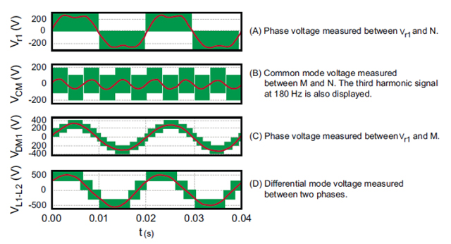
Figure 1: Simulated Voltage Waveforms of the Three-level Active Bridge together with the Corresponding Average Value
As a result of the switching actions, both differential mode (DM) and common mode (CM) voltages are generated. A CM voltage is a voltage common to all three phases of the DC bus.
The CM voltage can be measured between the midpoint M of the two DC-bus capacitors and N. See Figure 2(B). In addition to the high-frequency CM voltage, the third harmonic signal is also visible in Figure 2(B). In three-phase systems, the total phase voltage vr consists of a DM voltage component and a CM voltage component that are equal in all three phases. The phase-related DM voltage can be measured between vr and M, resulting in the actual voltage component used to shape the input mains currents. The CM voltage component has no influence on the current shaping of the phase currents, but its associated high-frequency components may cause unwanted effects.
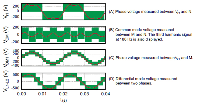
Figure 2: Simulated Voltage Waveforms of the Three-level Active Bridge together with the Corresponding Average Value
It is common to plot the differential voltage as the voltage measured between two phases, as shown in Figure 2(D). This relationship between CM voltage and associated high-frequency components is common when studying active rectification topologies. All voltages show high-frequency components, and their average values (averaged over one switching period) are either used to shape the mains currents or show the third harmonic component used to increase the voltage range.
Reduction of CM Voltage
In addition to the intentional DM voltage component, which is used to help shape the input current waveforms, some high-frequency CM voltage is present. This CM voltage adds to the CM voltage already being generated by the inverter stage of the drive. This results in undesirable high-frequency CM voltage variations of both the DC bus and total CM voltage. High-frequency CM voltage and its high dV/dt are the main sources of bearing currents, which are known to reduce the service life of the bearings, or even destroy them in a very short period of time.
A typical, passive diode bridge rectifier has only the CM voltage generated by the inverter stage of the drive present. By contrast, an active rectification drive adds CM voltage, which increases bearing currents. The amount of CM voltage added is dependent on the topology and the implementation. Schneider Electric’s low harmonic drive topology shows considerably smaller CM voltage than other classical two-level topologies, approaching the level that exists with typical passive diode bridge rectifiers.
In Table 1, the CM voltage of a two-level AFE is compared to the CM voltage of a three-level design. Whereas the two-level AFE shows CM voltage levels of ±VDC/2 and ±VDC/6 and voltage steps of ±VDC/3, the three-level design shows only voltage levels of ±VDC/3 and ±VDC/6, which result in voltage steps of only ±VDC/6, a total reduction of 55 Vrms. The reduction of CM voltage levels and, consequently, the CM voltage steps applied to the motor, reduces the stress of the insulation and reduces the bearing currents. However, the dV/dt of 2–5 kV/μs still remains—a main cause of the high-frequency currents in the bearings.
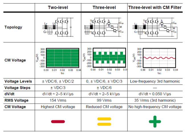
Table 1: Comparison of CM Voltage Increase Across Technologies
Because bearing currents and the service life of bearings are among the main concerns with VFDs, a CM voltage reduction method can be implemented in the three-level topologies. Schneider Electric’s low harmonic drive accomplishes this by connecting the DC bus voltage midpoint M to the artificial star-point built by the filter capacitors CF as shown in Figure 3. With this connection, the additional high-frequency CM voltage is nearly eliminated. An equivalent circuit of the CM filter is shown on the right side of Figure 3. The total CM voltage VCM consists of a high-frequency component VCM,HF and a low-frequency component VCM,~.
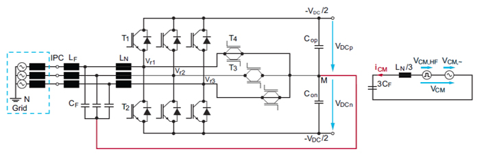
Figure 3: Three-level Design with CM Filter Reduction
The elimination of this high-frequency voltage component (VCM,HF) is critical for prolonging motor service life. The combination of the boost chokes and filter capacitors results in a second order low pass filter which attenuates the CM voltage components at the switching frequency and at multiples of the switching frequency. Only the low-frequency CM voltage remains across the filter capacitors and can therefore be measured at the DC bus voltage midpoint M.
A resonant tank for CM signals is built by the filter capacitors CF and the boost chokes LN. The resonant tank could be excited by the active rectification, which actively dampens the input filter stage. Due to this active damping of the CM filter stage by a dedicated controller, damping resistors with high dissipative losses are not required, resulting in no additional losses within the drive.
As shown in the “Three-level with CM Filter” graphic, no high-frequency CM voltage caused by the three-level design is present at the DC bus. Only the CM voltage generated by the inverter stage (not shown in Table 1) remains at the same level as that of a drive with a traditional diode bridge, something that has been used in industrial applications for decades. This is a tremendous improvement, as a low-harmonic input stage using this concept doesn’t increase CM voltage and doesn’t increase bearing currents. With this technology, it is possible to replace a passive diode bridge rectifier with a low-harmonic input stage, with or without energy recovery.
This article is part of a five-part series looking at new technologies in harmonic mitigation – including the industry’s first three-level low-harmonic drive – designed to uniquely address the harmonics issue. For more information, please visit: goo.gl/zFuMXf.
About the Author
Garrett Abbott-Frey is the U.S. Process Drive Offer Manager in the Industry Business of Schneider Electric. Based in Raleigh, North Carolina, Garrett brings nearly 5 years of professional experience to the role drawing from previous positions in OEM Machine Design and Electric Motor and Drives validation and testing. He currently focuses on Enclosed Drive Systems targeting the upstream Oil & Gas industry to support production process optimization for customer Artificial Lift applications. Garrett has led numerous training sessions on harmonics, drives commissioning, and other drives-related topics as well as recently publishing the whitepaper, “Transformation from Six-Pulse to Low Harmonic, Three-Level, Active Rectification Technologies.” He has a bachelor’s in Mechanical Engineering from North Carolina State University with a focus on Physics and Environmental Science.
Jack Creamer is Schneider Electric Segment Marketing Manager – Pumping Equipment, based in the United States. Mr. Creamer has more than 30 years in the Electrical Industry, and has been involved for 10 years in the Pumping Industry. He is involved in key industry organizations such as the Hydraulic Institute and Submersible Wastewater Pump Association, where he holds both Committee Chair and Board level positions. In his time in the Pump industry, he has help Schneider create numerous solutions that both enhance pumping efficiency and address issues such as maintenance and downtime.


Comments