Authors: Garrett Abbott-Frey, US Process Drive Offer Manager – Industry Business, Schneider Electric, and Jack Creamer, Market Segment Manager, Pumping Equipment – Industry Business, Schneider Electric
As VFDs gain increasing acceptance in the Pumping Equipment market, application challenges come to the surface, of which Harmonics is one key example.
What is Harmonics and Why is it an Issue?
To understand harmonics, you first must understand types of loads in variable frequency applications – linear and non-linear. A linear load is where the current waveform has the same shape as the supply voltage. A non-linear load is where the current waveform changes with the supply voltage.
Non-linear loads are common in all industries, including pumping applications, and are often caused by equipment, such as welding machines, induction furnaces, power supplies, and even variable frequency drives (VFDs). VFDs have input rectifiers which produce an input current that is very non-sinusoidal. These currents can be represented by a sinusoidal fundamental current and additional sinusoidal harmonic currents. A high level of harmonics could affect the efficiency and performance of other electrical devices connected to the same input power supply.
To improve power quality in the electrical systems, many types of harmonic mitigation architectures can be deployed. These non-linear loads are the source of harmonics which can disrupt the control infrastructure supporting your pumps. This can result in unwanted equipment behavior and even power loss. Harmonic content in power distribution systems can lead to various undesired outcomes, such as disturbances in communications, increased operational expenses, and loss of revenue.
The Results of Harmonics
Power distribution systems typically include various types of power components such as reactors and transformers. As current flows through these electrical components, each component introduces a level of impedance. With the introduction of impedance in the system, a certain level of voltage drop is expected. This voltage drop is directly proportional to the total amount of current flowing through the given system.
Harmonic currents cause voltage distortions and power quality issues that impact each electrical component in the system. This can result in unwanted equipment behavior and even power loss. Harmonic content in power distribution systems can lead to various undesired outcomes, such as disturbances in communications, increased operational expenses, and loss of revenue.
In addition, some system loads drawing harmonic current often draw currents which result in increased ground currents and/or induce common mode noise. This can cause increased motor bearing temperatures in three-phase induction or permanent magnet motors. Both of these conditions can negatively impact the service life expectancy of the equipment connected to the power grid.
Mitigation Architectures Overview
The most obvious impacts of harmonic distortion are increased current draw and deterioration of power quality, which have both a technical component and financial impact on end users. A variety of methods can be used to mitigate harmonic distortions. Some involve additional cost in the overall power system. Some methods also provide additional benefits outside of harmonic mitigation. These benefits will be explored in depth.
Multi-pulse Input Rectification
A comparison of 6-, 12-, and 18-pulse rectifiers is presented in the following paragraphs. 6-pulse Rectification Standard VFDs use 3-phase power with 120° of phase shift and have a full wave rectifier using six diodes, as seen in Figure 1. Whenever the input voltage for a line-to-line phase is higher than the DC bus voltage, two of the diodes will conduct and the current will charge the DC bus.
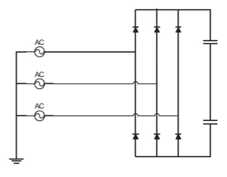
Figure 1: 6-pulse Input Electrical Drawing
Because the DC bus voltage is near the peak of the AC line voltage, the diodes only conduct during the peak of the incoming waveform. The amount of peak current will be limited by the power system impedance. The resulting current waveform, as shown in Figure 2, has a double peak pattern with narrow current spikes.
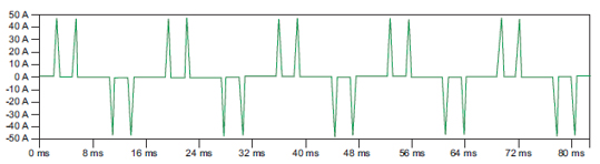
Figure 2: 6-pulse Input Current Waveform without Input Impedance
By adding a line reactor, the peaks can be reduced, but not eliminated, as shown in the waveform in Figure 3. The peaks are reduced and the pulses are wider so the same amount of energy is going into the drive. Although this has lower harmonic content (as compared to not using a line reactor), it still has a significant amount of harmonics—around 40% or more.
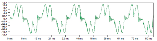 Figure 3: 6-pulse Input Current Waveform with Input Impedance
12-pulse Rectification
If a Delta-Wye transformer is used, there is a 30° phase shift between each set of the transformer windings. By using a six-diode rectifier on the Delta secondary winding, and another six-diode rectifier on the Wye secondary winding, a current waveform with a stronger middle peak occurs, making it begin to approximate a sine wave. As a result, the first significant harmonic current lobes are displaced from 5th and 7th harmonics to 11th and 13th harmonics. Harmonics are around 12% if the voltages are balanced.
18-pulse Rectification
Increasing to 18 pulses results in even more current smoothing. A special transformer with 9 secondary windings feeding the diode bridges is used. An 18-diode rectifier is used to rectify the power, resulting in an input current waveform that is substantially a sine wave with minor variations. Current harmonics (THDi) are around 5% if the voltages are well balanced. If the voltages become unbalanced, the effectiveness of the current harmonic reduction will be minimized. The addition of this special transformer results in additional cost and heat dissipation, which impacts the overall VFD efficiency and makes 18-pulse solutions potentially more expensive than 6-pulse or passive filter solutions.
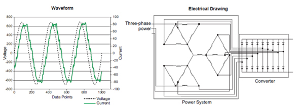
Figure 4: 18-pulse Design
Broadband Filter
The broadband filter reduces the harmonics by storing energy in inductors and capacitors. By filtering out the 5th and 7th harmonics, a sine wave can be produced on the input current while still providing adequate charging current to the VFD. However, a leading power factor can occur at light loads, which can be corrected by adding a contactor to disconnect the capacitors. Unbalanced voltages are managed better than in the 18-pulse design. Some broadband filters may boost the voltage too much and cause the drive to trip on overvoltage; others have the filter tuned broadly enough that this does not occur. Figure 5 shows a one-line diagram for the broadband filter.
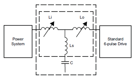
Figure 5: One-Line Diagram of a Typical Broadband Filter
This article is part of a five-part series looking at new technologies in harmonic mitigation – including the industry’s first three-level low-harmonic drive – designed to uniquely address the harmonics issue. For more information, please visit: goo.gl/zFuMXf.
READ PART 2: Active Front End Drives and How They Work
About the Authors
Garrett Abbott-Frey is the U.S. Process Drive Offer Manager in the Industry Business of Schneider Electric. Based in Raleigh, North Carolina, Garrett brings nearly 5 years of professional experience to the role drawing from previous positions in OEM Machine Design and Electric Motor and Drives validation and testing. He currently focuses on Enclosed Drive Systems targeting the upstream Oil & Gas industry to support production process optimization for customers Artificial Lift applications. Garrett has led numerous training sessions on harmonics, drives commissioning, and other drives-related topics as well as recently publishing the whitepaper, “Transformation from Six-Pulse to Low Harmonic, Three-Level, Active Rectification Technologies.” He has a bachelor’s in Mechanical Engineering from North Carolina State University with a focus on Physics and Environmental Science.
Jack Creamer is Schneider Electric Segment Marketing Manager – Pumping Equipment, based in the United States. Mr. Creamer has more than 30 years in the Electrical Industry, and has been involved for 10 years in the Pumping Industry. He is involved in key industry organizations such as the Hydraulic Institute and Submersible Wastewater Pump Association, where he holds both Committee Chair and Board level positions. In his time in the Pump industry, he has help Schneider create numerous solutions that both enhance pumping efficiency and address issues such as maintenance and downtime.