By Jeff Sietsema and Rick Foster
Coriolis mass flow meters do not measure flow directly in terms of gallons per minute (gpm) or cubic meters per hour (M3/hr). Instead, fluid density and the coriolis forces (mass flow) are measured, which are then used to calculate flow rates.
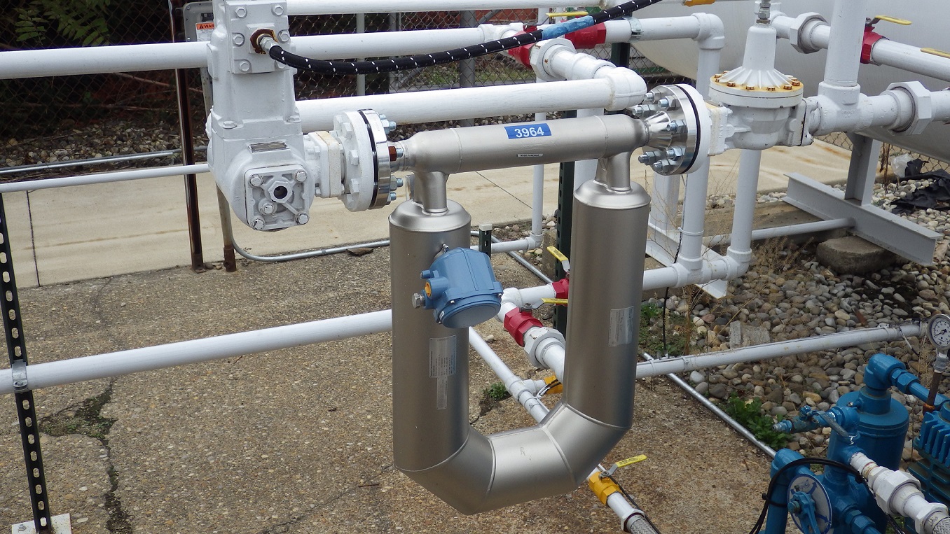
There are typically two measuring tubes in a Coriolis meter, which are formed into a slightly bent tube or a more dramatic “U” shape. The measuring tubes through which the fluid flows are constantly expected to oscillate at their resonance frequency. The resonance frequency is the frequency at which the measuring tubes are “most willing” to oscillate. Any change in the density of the fluid produces a corresponding change in the resonance frequency of the entire vibrating system (measuring tube and fluid). The resonance frequency, therefore, is a function of fluid density – the higher the density, the lower the resonance frequency. The resonance frequency is then compared to the empty-tube resonance frequency, allowing the mass of the fluid in the tubes to be calculated. Since the volume of the tubes is known, the density of the fluid can be calculated.
Typically, the two tubes in the meter are vibrated 180 degrees out of phase with each other. As flow (mass) passes through the meter, the phase angle between the tubes changes. The phase-angle change of the tubes is caused by the Coriolis Effect and is proportional to the mass flow rate of the fluid in the tubes. Using the mass flow rate and dividing by the density provides a volume flow rate. Both the density and the mass flow rate are measured directly and are therefore independent of the temperature, pressure, viscosity, conductivity and flow profile of the fluid passing through the meter. This means that, in theory, a Coriolis mass flow meter can be used to measure any type of fluid flow. The meter output can be corrected to a standard reference temperature if desired.
There are several significant advantages to using Coriolis mass flow meters:
- Because the flow passes through smooth tubes with no moving parts, there is no mechanical wear of the measuring elements. There are also no parts subject to abrasion, erosion or corrosion.
- Particulates nearly as large as the measuring tube diameter can pass through the meter without issue. Typically, the measuring tubes have a diameter one-half that of the meter’s piping connections for a two-tube meter and are approximately equal to the piping connections for a single-tube meter.
- Coriolis meters are not affected by temperature or pressure. They measure mass flow directly, which does not change even if the temperature or pressure of the fluid changes. Therefore, no pressure or temperature compensation is required.
- Accuracy is typically listed as 0.1% to 0.2% of the flow rate being measured. This is much more accurate than mechanical meters, which are listed as being within 0.5% of full-scale flow. Because other types of meters also need to have pressure and temperature compensation, additional error in these measurements can increase the overall flow error to as much as 3%.
- Because of their very precise accuracy, the Coriolis flow meters have a turndown ratio of about 100:1 or more. This means that if a meter is rated for a maximum flow rate of 200 gpm, it is still accurate down to 2 gpm. Typical mechanical meters have a turndown ratio of 10:1. An orifice plate’s turndown ratio is more like 5:1.
- There is minimal pressure drop through a Coriolis mass flow meter with lower-viscosity fluids. The only pressure losses are caused by the splitting of the flow into the two measuring tubes. Orifice plates, flow nozzles, venture tubes and positive displacement meters can have significant pressure losses associated with the meter.
- Coriolis meters are unaffected by changes in viscosity during a process or batch run. Orifice plates and the other pressure-differential meters need to be calibrated for various viscosities and the viscosity needs to be measured during operation to ensure accurate metering.
Admittedly, there are also a few disadvantages to using Coriolis mass flow meters that must be considered:
- Pressure drop through a Coriolis meter may increase significantly with increasing viscosity when compared to other technologies such as ultrasonic or magnetic flow meters. The pressure drop is caused by the split of flow into two or more smaller pipes that are not straight. The smaller bent pipes can increase pressure drop when compared to the straight-through flow of ultrasonic or magnetic flow meters.
- Typically, a mass flow meter has a higher initial cost than that of other technologies for similar applications.
- Depending on the amount of “bend” in the measuring tubes, the space required to locate a Coriolis flow meter can become significant. However, this is offset by a reduction in the amount of straight pipe (flow straightening) usually required on the inlet and discharge sides of many types of flow meters.
Mass flow meter experience at Blackmer®
To understand how Coriolis mass flow meters might interact with Blackmer® sliding vane pumps, two flow meters were purchased. The first meter, from Endress+Hauser, was a 3″ Model 83F. This meter was used for performance testing of various pumps on 30-SSU through 2,000-SSU fluids. The second meter, an Emerson™ Micro Motion 2″ Model CMF200, was installed on Blackmer’s propane test loop. Meters were evaluated for setup and installation, pressure pulses and flow precision.
Setup and Installation:
The Endress+Hauser meter was installed on a mobile cart. A 3″ 100-mesh strainer was installed on the inlet side. The piping looped around on the cart with an elbow directly on the inlet side of the meter. This was done because, per the recommendations of both manufacturers, no straight-line inlet piping is required on the inlet or the outlet side of the meter for straightening. Manufacturer recommendations were to install the meter vertically to allow easier removal of air when the meter is started empty. However, the meter was deliberately installed horizontally to investigate the effects of improper meter mounting orientation. Typical usage for this meter was to test a pump with a specified fluid and viscosity, drain the pump and piping system, and then set it up with another pump with a specified fluid. The Endress+Hauser meter has a flow capability of 800 gpm of water.
The Emerson meter was also installed in the LPG test loop horizontally. However, in keeping with LPG custody transfer protocol, a vapor eliminator and back-check valve were installed with the meter. This system is also used in a similar manner: a pump is tested, piping is drained and the pump is removed for the next pump installation. The Emerson meter has a flow capability of nearly 400 gpm of water.
The following observations and lessons were learned from using the meters:
- Both meters have pressure-pulse dampening software available. Both meters had this feature deactivated; testing indicated that it was not necessary.
- Flow readings were unexpectedly smooth on both meters, much less than with any PD meters that were used previously. Fluctuation of the Emerson meter on LPG was observed to be ±0.1 gpm for flows to 40 gpm. The Endress+Hauser meter fluctuation was similar, with fluctuations up to perhaps ±0.3 gpm on flows up to 300 gpm, and greater.
- The Coriolis mass flow meters are acoustically much quieter than PD meters. This was especially noticeable with the meter on the LPG system. Because there are no moving parts there is no vibration generated to resonate with associated piping. However, when the meters are powered and not filled with liquid, they do emit a high-pitched hum. The humming can be eliminated by keeping the meters filled with liquid or by de-energizing the meters.
- The LPG meter, with the vapor-elimination system, experienced no difficulties reading flow when started empty. Since the back-pressure and vapor-elimination valves eliminated vapor quite well, the meter filled with liquid as quickly as the PD meter used earlier.
- There was difficulty getting rid of air from within the Endress+Hauser meter, which had been intentionally mounted horizontally on the mobile cart. Both manufacturers recommended the meters be installed vertically and the recommendation was proven correct. Above flow rates of 100 gpm, air was successfully removed in a very short time (less than one minute). At lower flow rates (less than about 75 gpm), a valve was used to throttle the outlet of the meter to increase pressure in the meter. This allowed the trapped air to dissolve in the test fluid and flush out of the meter after several minutes. Below about 30 gpm it was not possible to completely get rid of the air.
- Air in the meter creates turbulence and reduces the accuracy of the density measurement. Air in the meter also causes the density measurement to become unstable, which could be observed on the meter register. When functioning properly, density fluctuation was typically ±.0005 SG or less – the fluctuation was out to the fourth decimal point, or in the ten-thousandths range. When air was in the system the SG varied approximately ±.05, or two orders of magnitude greater than without air.
- The Endress+Hauser meter was re-orientated vertically to test the air-elimination process. At a flow rate of less than three gpm, (on an 800-gpm meter) after about five minutes of operation, it was possible to flush the air out of the meter without using a throttling valve on the outlet side of the meter. With more flow rate, or by throttling the outlet of the meter, air removal was accomplished in less time.
Pressure Pulses:
A point of concern when utilizing Coriolis mass flow meters with positive displacement pumps is that PD pumps generate pressure and flow pulses that a Coriolis meter might respond to. PD pumps move fluid by filling a fixed-volume chamber and then forcing the fluid out of that chamber. The PD pump could have as few as one chamber, such as a single-piston pump, or 20 or more, as in a gear pump. The pressure pulses are generated by each individual pumping chamber being filled and emptied, and the frequency of the pulses is a function of the number of chambers in the pump and the speed at which the pump is operated. Coriolis mass flow meters measure vibration of the tubes and frequency variation of the tubes in order to measure flow. We wanted to understand if the vibrations generated by Blackmer sliding vane pumps would interfere with the flow-meter measurements.
Distortion of flow-meter vibration measurements would, in theory, tend to be maximized near the frequency at which the flow meters operate. From discussion with the mass flow meter manufacturers, the resonant vibration of the mass flow meters is approximately 200 Hz. To evaluate possible interference of pressure pulses with flow measurement, several sliding vane pumps were tested at a nominal 100 psi with varying shaft speeds to create a range of vane frequencies from 80 Hz to 260 Hz. High-speed pressure and flow data was collected and minimum and maximum pressures and flows were recorded. The results indicated that there was no correlation between the vane frequency, pressure pulsing and measured flow at the meter.
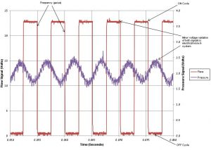
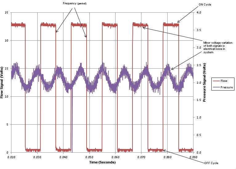 Another attempt was made to look for possible interference between the pump and the flow meter. A pump was operated at sliding vane frequencies of 120 Hz and 200 Hz (Figure 2 and Figure 3) for comparison, with pressure on the pump outlet and in the flow meter held at a nominal 100 psig. The flow and pressure signals from the flow meter and the pressure transducer were monitored with a digital-signal processing oscilloscope.
 The Coriolis flow meter used for the test provided a frequency output signal, producing a 50% on/off square-wave function between 0.5 VDC and 22.5 VDC. The number of on/off cycles produced by the meter per unit of time is proportional to the flow passing through the meter. While operating at the conditions outlined above, the signal from the flow meter was inspected for distortions of voltage values, shape of the output function and the timing of each signal step over time. Other than minor
 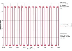 pressure and flow fluctuation that were within the expected values of the system, no significant output-wave from distortions were found. Figure 2 and Figure 3 show samples of the results.
The final investigation pursued was to operate a sliding vane pump with the vane-pass frequency the same as the Coriolis mass flow meter’s resonant frequency and record that output wave form from the meter and then compare it to the same conditions with non-pulsed flow from a rotodynamic flow source. The vane pump was operated at a sliding vane pass frequency of 200 Hz to maximize the opportunity for meter resonance. The flow rates and operating conditions for both pumps were held equal at 19.5 gpm and 100 psig on 30-SSU solvent. The results (Figure 4) show that the wave forms are identical. The meter handled both types of flow (pulsed and non-pulsed) with equal precision.
Flow Precision:
A test was designed to demonstrate and compare the accuracy of the Coriolis mass flow meter and the positive displacement meters historically used at Blackmer’s Research & Development Laboratory. To 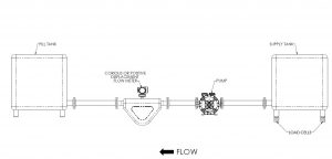 provide an alternate method of measuring flow, a 300-gallon tank was placed on four 500-pound precision NIST-traceable load cells. The load cells and electronic instrumentation were selected so that the precision of the weight-flow measurement would have a tighter tolerance than the mass flow meter at some of the lower flow rates. A pump and the test
 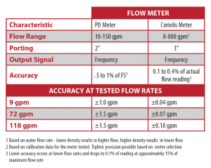 flow meter were piped to another tank such that all the flow moving from the supply tank was metered as it entered the fill tank. The test pump was operated at constant speed with minimum back pressure (no valve throttling) to obtain a constant flow rate while emptying the supply tank. The weight of the supply tank was recorded every 0.1 seconds so that a mass flow rate could be directly recorded. The density of the water was measured with an NIST-traceable hydrometer so the mass flow rate (lbs./sec) could be converted into a gpm flow rate. A drawing of the test setup is shown below (Image 1), as well as a chart of the characteristics of the flow meters tested (Figure 5):
Three basic flow rates were tested: 9 gpm, 72 gpm and 118 gpm. Data was collected the entire time the pump was in operation, recording flow-meter readings and the weight of the supply tank. About five seconds after pump startup, flow became very consistent until the supply tank was nearly emptied. The data from the steady-state flow intervals is shown in the following graphs (Figures 6-11):
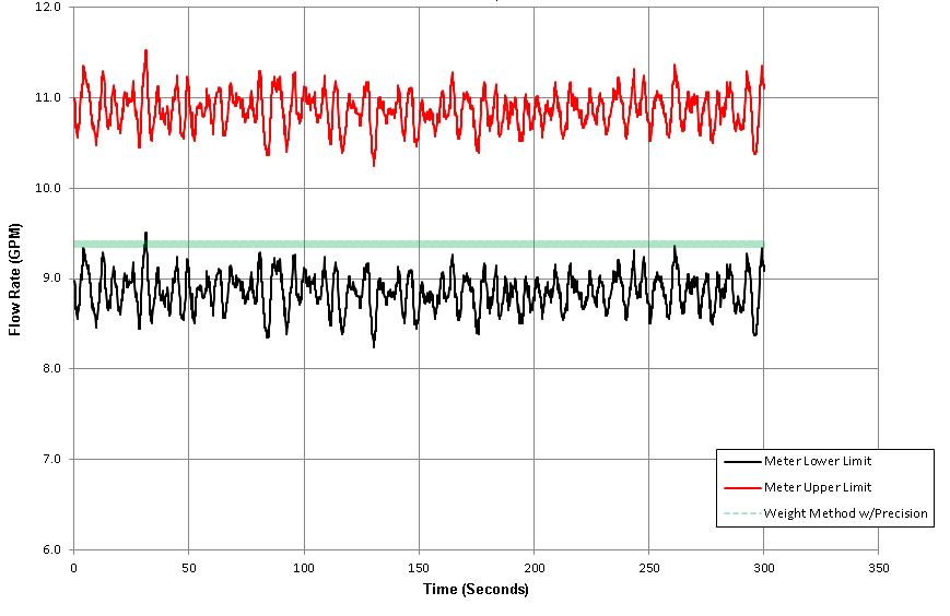
The graphs show the precision of each test meter and the precision of the weight method of flow measurement. Precision of the flow meters is the published calibration/ accuracy specifications at the tested flow rates. The weight-method precision is a function of the accuracy of each load cell, the amount of weight that was moved during the measurement and the amount of time required to move themeasured weight. The low flow rate (9 gpm) produced the most precise weight-measured flow 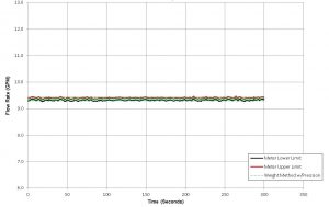 because more time was required to remove the approximately 900 pounds of water. As flow rate was increased, less time was required and the weight-method precision tolerances increased.
As can be seen, the precision of the Coriolis meter is much tighter than the positive displacement meter, and was as precise as the weight method at 9 gpm and more precise at the higher flow rates. The Coriolis 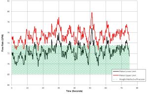 flow meter and the weight method have a high degree of correlation and statistically are indistinguishable over the entire time and range of flow measured. On the other hand, the positive displacement meter, with a much wider precision range, does not conform as well to the weight method of flow measurement.
An unanticipated error of the weight method did occur during the 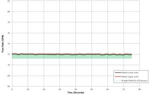 precision tests. It was observed that the weight measurements fluctuated much more than the precision of the load cells would indicate. The tank of water, sitting on four load cells, inadvertently became a spring-mass system. The weight on the load cells fluctuated with system vibrations,such as mechanical vibration and pressure pulses from the pump. To correct for this, the weight uncertainty was estimated by
 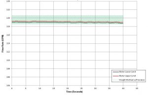 comparing the theoretical mass flow (overall weight change compared to overall time passed) to the actual observed weight loss for each recorded time interval. The average fluctuation for all of the time intervals was added to the overall precision of the weight method, increasing the tolerance of the flow rate. The interesting thing about this is that the positive displacement meter consistently produced more weight variation than the Coriolis flow meter. As can be
 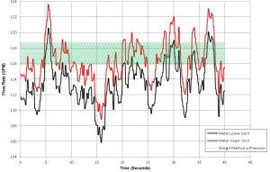 seen on the precision graphs, the tolerance of the weight-method flow rate is larger for the PD meter than the Coriolis flow meter, even though the flow rates are nearly identical. The widest discrepancy was observed at the mid-range flow rate. Earlier discussion of how pressure pulses may affect the Coriolis flow meter showed that this was not observed in the tests conducted. The system did not seem to affect the meter. The opposite of that was proven during the weight-method precision test; the meter has an effect on the system. While the effects of the Coriolis flow meter could not be separated from pump variations, the positive displacement meter effects are quantifiable.
Observations from the field
The decision to invest in Coriolis mass flow meter measurement technology in Blackmer’s Research & Development Laboratory and production facilities was based on observations from Blackmer’s customer base. Many Blackmer customers have evaluated Coriolis flow meters and found them to be the best flow-measurement solution in systems where Blackmer pumps are applied. Increased flow-measurement precision and higher reliability were the most common improvements cited by end-users. The photograph on the cover of this report was taken at one of these facilities utilizing Blackmer GX Series Sliding Vane Pumps for liquid transfer. EMCO Chemical Distributors, Inc., Pleasant Prairie, WI, USA, reports excellent results using Blackmer sliding vane pumps in systems that use Coriolis flow meters for flow measurement. A recent multiple pump installation at EMCO for railcar unloading has yielded highly reliable system performance and excellent measurement accuracy with no reported problems after 18 months in operation.
Blackmer sliding vane pumps are often applied in fuel-transfer applications. Blackmer provides pumps to major petroleum distributors that have switched from positive displacement meters to Coriolis mass flow meters in systems where Blackmer pumps were installed. Again, information from the field is positive in the installed base where
Blackmer sliding vanes pumps are used in conjunction with the Coriolis flow meters. This further supported Blackmer’s decision to investigate—and, ultimately, invest in—the technology.
Discussion and Conclusions
- Flow meters from two highly respected equipment manufacturers were purchased in an effort to eliminate possible bias between “brands” of the same technology.
- One unexpected observation that was discovered during testing was in noise generation. In both LPG and solvent tests, Coriolis mass flow meters (from both manufacturers) operated with less airborne noise than the positive displacement (PD) meters that Blackmer had been using. The PD meter devices generated their own pressure pulses in the discharge line. We had become accustomed to the noise and had accepted it. We were very favorably impressed with how quiet the new meters were in operation.
- We attempted to operate the sliding vane pumps at speeds where the pressure-pulse frequencies would be at the same resonant frequencies as the Coriolis flow meters themselves. We then varied the speeds to levels (pressure-pulse frequencies) above and below the meter’s published natural frequency. We could not induce any constructive or destructive interference into the vibrating Coriolis tubes by intentionally operating them in the natural frequency range of the tube spring/mass system. Nothing we could do within the normal operation of the pumps caused any degradation of meter accuracy.
- Proper mounting of the meter was found to be critical for accurate and reliable meter performance at low flow rates. Mounting the meter horizontally was the only application parameter that we determined to have an effect on the meters.
- Measurement precision and repeatability were markedly better with the Coriolis flow meters than Blackmer’s PD flow-measurement technology. This was determined by measuring the weight (mass) of the liquid pumped with highly accurate NIST-traceable load cells to verify the actual performance of both the PD meter(s) and the Coriolis mass flow meters.
- Blackmer’s customer base has a great deal of experience using Blackmer pumps with Coriolis mass flow-measurement technology. We have had no reports from the field of any incompatibilities or other issues to date after many years of service.
- The meter test results from Blackmer’s Research & Development Laboratory have been compelling enough to convince us to install the Coriolis flow meters on our production test stands. We have installed an Endress+Hauser mass flow meter on one of our production pump test rigs. This rig tests three different sizes of Blackmer sliding vane LPG pumps daily. We have experienced greatly improved measurement accuracy and very good reliability in a production environment.
About the Authors:
Jeff Sietsema has worked at Blackmer for 27 years. As a Product Development Engineer he worked in the development of both military and commercial positive displacement pumps. He is currently serving as the Research & Development Lab Manager. Jeff holds a B.S. degree in Engineering from Calvin College in Grand Rapids, MI, USA.
Richard E. Foster started his professional career with Fema Corporation of Portage, MI, USA, as a Product Development Engineer and was responsible for the design of electro-hydraulic pressure control valves. He joined Blackmer in 1990 as a Product Development Engineer before being promoted to Engineering Manager. He left Blackmer to start his own manufacturing company in 1998 before returning as Director of Engineering in 2011. He holds a B.S. and M.S. Engineering from Western Michigan University in Kalamazoo, MI, USA.
Blackmer® is the leading global brand of innovative and high-quality rotary vane and centrifugal pump, and reciprocating compressor technologies for the transfer of liquids and gasses. For more than a century, the Blackmer name has stood for unparalleled product performance, superior services and support, well-timed innovation and a commitment to total customer satisfaction. Supported by a worldwide network of distributors and original equipment manufacturers, Blackmer pumps and compressors are used in a multitude of applications in the Process, Energy and Military & Marine markets. Blackmer—headquartered in Grand Rapids, Michigan, USA—is a brand of PSG®, a Dover Company, Oakbrook Terrace, IL, USA