Authors: Bruce Ellis and Stephanie Jouppien, Triangle Fluid Controls
When it comes to check valves or one-way valves, the properly sized valve is the best preforming valve. As simple as this logic is, check valve sizing is largely misunderstood. Check valve “sizing” refers to how much the valve’s disc opens in order to accommodate media flow through a pipe – a vital component to the system’s overall functionality. Engineers typically oversize their designs anticipating a greater demand or line capacity down the road, however, it’s usually more than is necessary and many projects are already over-specified when designed. A good place to start with check valve sizing is to ask yourself: “What will the check valve be used for 90% of the time?”
Check valves should be specified for the current application and can be re-sized at a later date to fit future requirements.
Check Valve Chatter: It’s Trying to Tell You Something
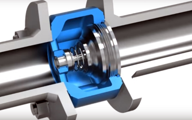
Valve sizing is by no means a new topic. Valve manufacturers have long recognized the importance of proper sizing and how often it’s misinterpreted in the field. It’s important to point out that unlike a standard open-close valve, check valves are flow sensitive. They are designed to allow fluid, steam or gas to flow in one direction. As the flow ceases, the valve’s internal disc automatically closes [see below video animation for more info]. Let’s say a project is over specified to use 6” piping where 4” would be suitable for its current use. In this instance, a 6” valve would be needed but is not the flow rate maximum (the maximum volume of media that travels through a pipe in one minute). A regular 6” valve used in this manner would be subject to pressure loss and would not fully open, causing it to flutter against its internal stop, making chattering sounds due to unstable flow. This will significantly shorten the valve’s lifespan by causing wear on the metal internals or by causing the disc to become stuck open, possibly leading to complete valve failure. Though less common, there are instances in which valves are undersized or under-spec’d which leads to a flow restriction.
How to Calculate Valve Size
In order to properly size a check valve, you must have viscosity of material, media, pressure, temperature and flow rate (defined as: the number of US gallons of water per minute at 60°F that will flow through the valve with a pressure drop of 1 psi) to be able to customize a centre-guided check valve to the application – this involves changing the distance the disc travels from the closed to full open position. When the valve’s disc is stable and fully open or closed against the seat, no fluttering, chattering or excessive vibration will occur.
Tips & Tools for Sizing
DFT Inc. has a sizing program that uses the required information from above to calculate the required amount the valve must open to accommodate flow volume. This calculation is used to make a travel stop that is installed in the valve. The disc will be able to fully open against the stop, keeping it stable in the flow.
 For further reading on check valve sizing, we recommend reading “Common Mistakes in Check Valve Sizing,” a free eBook from DFT Valves. If you prefer a more personalized approach to sizing for a custom application, fill out this contact form to have a check valve expert follow up with you.
Proper sizing is essential and will ensure that the valve works at peak efficiency and will require less downtime, maintenance or result in a dreaded system failure. Happy Sizing!
Learn more about Silent In-Line Check Valves from DFT Valves Inc.


