
Author: Daisy Ambach, Hatch, United Kingdom
Applied Flow Technology Platinum Pipe Award Winner: Correlation to Test/Field Data
Daisy Ambach, Junior Process Engineer for Hatch, worked with a hazard and operability study (HAZOP) committee to re-validate the design and operation of a production facility in the North Sea. The committee was asked to work in accordance with regulatory requirements to identify any safety critical issues and recommend appropriate actions. They identified a range of actions related to relief and blowdown, piping, and flow assurance.
During the initial HAZOP study, it was noted a surge analysis had not been conducted for the water injection system and the committee deemed there was limited understanding of pressure surge protection. In case of a remote facility trip or a closure of a shutdown valve in the system, the only safeguard in place for pressure surges was the piping design pressure.
“The advanced level of analysis and simple user interface, the computational architecture of the software allowed waterhammer calculations to be performed for a large piping system within a small time frame.”
It was unclear whether the design pressure of the existing piping was rated to the maximum expected overpressure in the event a remote facility was to trip. The committee requested that Ambach complete a pressure surge analysis so they could understand pressure surge at current operating conditions as well as at the design conditions which was equivalent to the maximum expected flow rate to the water injection wells at each of the platforms.
The water injection system distributes water to injection wells across five platforms via three bridges and two subsea pipelines. Three turbine-driven water injections pumps (A, B and C) operate in a two-out-of-three configuration to transfer filtered, deaerated seawater to the injection wells. Pumps A and B are used to pump water to Platform C and the water injection manifold.
The flow to each of these lines is managed with flow control valves. Pumped seawater from Pump C is transferred directly to the water injection manifold from which water is distributed to injection wells at Platform B, D and E (Figure 1).
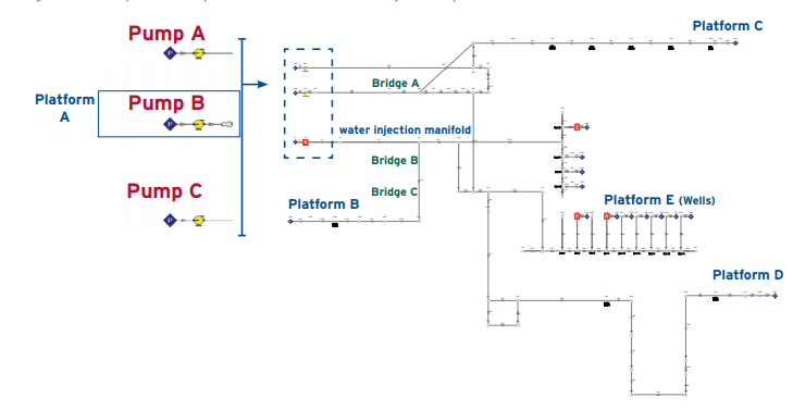
Figure 1: AFT Impulse Workspace view of the Sea Water Injection System
After the AFT Impulse model had been developed, it was necessary to complete model tuning and validation to ensure its accuracy. The model predictions at steady state operation are compared against operational data retrieved from the client’s control system in Figure 2.
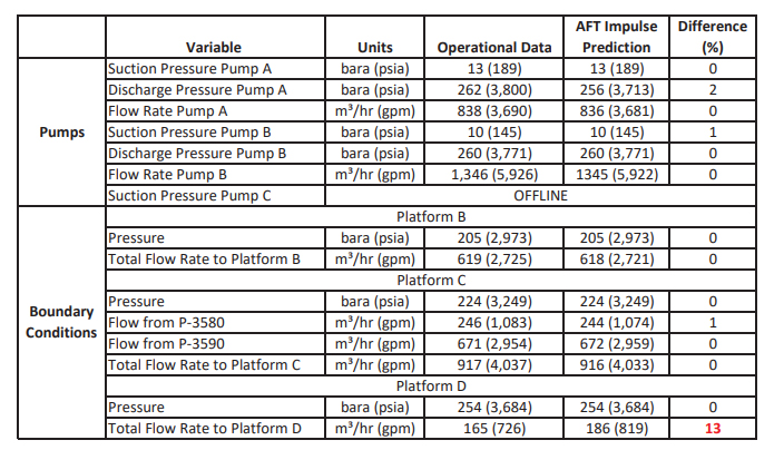
Figure 2: Comparison table showing AFT Impulse steady-state results vs. operational
measurements. Additional table results not pictured also show agreement.
There is a general agreement between the operational data and the AFT Impulse steady-state results, with most simulation results deviating from the operational data by between 0 and 8%. There is a marginally higher disparity in the flow rate to Platform D, which the model is predicting to be 13% greater than the flow rate at operation. This inconsistency can be explained by the difference in the inlet flow to the system and the outlet flow as per the operational data.
The simulation results show there are no scenarios in which the closure of a valve at current operating and design conditions within the water injection distribution system will cause the hydraulic pressure to exceed the design pressure of the piping.
“It was evident AFT Impulse better captured the effect of elevation profile changes and slower valve closure times on pressure surges. Tools within the ‘Graph Results’ functionality of the program allowed a large quantity of data to be analyzed effectively.”