Explore key facets of centrifugal pump ownership, installation, operation, and troubleshooting
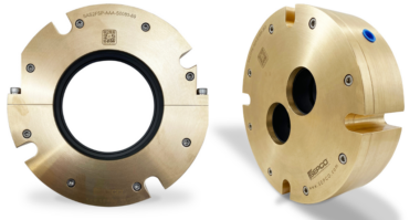
The Second Edition of Pump Wisdom: Essential Centrifugal Pump Knowledge for Operators and Specialists delivers a concise explanation of how pumps function, the design specifications that must be considered before purchasing a pump, and current best practices in lubrication and mechanical seals.
This new edition also contains new startup and surveillance tips for pump operators, as well as repair versus replacement or upgrade considerations for maintenance decision-makers, new condition monitoring guidance for centrifugal pumps, and expanded coverage of operator best practices.
Read Chapter 3: Foundations and Base Plates here.
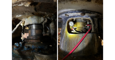
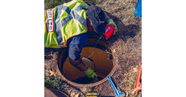
Monitoring pipe stress while bolting up
Pumps are designed to allow only limited loading of pump suction and discharge nozzles. Misaligned pipes can produce forces and moments on pump nozzles that vastly exceed maximum allowable values. Excessive piping loads can cause high vibration, shaft misalignment, seal distress, bearing overload, and coupling failures.
To keep within allowable limits, several dial indicators are set up to monitor the pump’s sensitivity to pipe stress. Dial indicator movement is monitored while initial and final bolt tightening is in progress. Four dial indicator stems are set to contact pump and driver feet to detect unsupported (soft-foot) conditions; two additional dial indicators observe the pump bearing housing for movement in the x and y-directions. Any indicator needle displacement in excess of 0.002 inches (0.05 mm) will require corrections to the piping.
Again, a process pump should never be allowed to serve as a pipe support. Chain-falls or come-along hoists and other supplementary mechanical tools (pulling devices) are never allowed or used by reliability-focused pump installation crews.
In general, maximum misalignment pipe flange to pump nozzle and flange-to-flange should be kept within the limits of Fig. 4.1. Before allowing connections to be made, the two mating faces should be
- Parallel with each other within 1/32 in. (0.8 mm) at the extremity of the raised face, i.e. “A” and “B” in Fig. 4.1 should differ by no more than 1/32 in (0.8 mm)
- Concentric so their centerlines coincide within 1/8 in, i.e., the offset “[C minus D]” should not exceed 1/8 in (3 mm).
There are two important, simple, yet very useful tests:
- It must be possible for an average-size worker to push the misaligned piping into place with his two hands, without using any supplementary mechanical tools
- Once the gasket has been inserted and the bolts have been torqued up, dial indicators observing the upwards and sideways motion at the pump suction and discharge nozzles cannot move in excess of 0.002 inches (0.05 mm) in any direction
Chapter 4, Reference 1: Bloch, Heinz P. and Fred K. Geitner; (2004), ”Machinery Component Maintenance and Repair,” 3 rd Ed., Gulf Publishing Company, Houston, Texas, ISBN 0-7506-7726-0.
Comments