Author: Heinz P. Bloch, P.E.
Attention should be given to oil levels needed and maintained in pump bearing housings. At relatively slow shaft speed/shaft diameter combinations, the oil level is adjusted to reach the center of the balls (or rollers) located at the 6 o’clock position of the bearing. However, at higher shaft speed/shaft diameter combinations letting oil reach to the center of a bearing ball would be inadvisable.
The dividing line is often made at a DN-value of 6,000. In the expression DN, D = shaft diameter in inches and N is the shaft RPM. Letting rolling elements plough through oil at high velocity would generate too much frictional heat. Therefore, if DN exceeds 6,000, the pump manufacturer designs bearing housings for oil levels well below the lowermost point of the bearings and uses different means to lift a small amount of oil into the bearings.
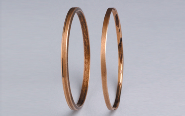
The most widely found means of bringing oil from the sump into the bearings is through the use of oil rings (see Figure 1 above). Unless carefully designed, fabricated and installed, oil rings are a risky item. Note a new oil ring to the left of Figure 1 and pay attention to the nice chamfers. These chamfers are completely worn off on the oil ring shown to the right of Figure 1. They are worn of for one or more of the following reasons:
- The shaft system was not completely horizontal, allowing the oil ring to run downhill and abrade. Brass slivers then contaminate the oil and wreck the bearing
- The oil ring did not undergo successive heat treatment (stress relieving) and finish-machining steps. It becomes out-of-round, slips, bounces, gets hot, malfunctions
- The oil was too thick (oil rings are designed for ISO VG 32), or the oil level was too high and the oil ring slowed down and perhaps even got stuck
If two or three of these deviations combine, the oil ring will not perform as expected and bearing life will suffer. If the resulting bearing life is 2 years, but your competitors do things right and their bearing life is 6 years, then you will have three times more failure events and your maintenance budget will be larger than normal.
The trouble with oil rings and constant level lubricators
Issues with oil rings are found in many scholarly works (Baudry and Tichvinsky, 1937; also Refs. 1 through 3. On a website post in September 2012, the Malaysian Government’s OSHA agency alerted readers to catastrophic failures brought on by oil rings (www.dosh.gov.my). All of these sources observed problems with oil rings, although an industry source opined (in 2011) that “ring lubrication is an accepted practice and it would take user consensus to damn it.” Of course, history shows us that innovations are rarely driven by consensus. If they were, the Wright Brothers would have worked on repeat pump and bicycle repairs instead of developing a powered flying machine. We tell you this because pump manufacturers will dispute this for all kinds of reasons and want you to think that field measurements and factual observation are mere fairy tales. Just because things worked on a factory test stand for three days does not mean things work in a plant after two years. Nothing will convince those who accept without questioning dozens of repeat failures of centrifugal pumps at their plants.
Many illustrations of failed oil rings are available. Studies, observations and measurements have shown the field reliability of oil rings in process pumps out of harmony with industry’s quest for higher reliability and availability. Work described by Wilcock and Booser, in 1957, recommends oil ring concentricity within 0.002 inches (0.05 mm). However, in 2009, shop measurements were performed by the author at a pump user’s site in Texas. The oil rings measured in 2009 exceeded the 0.002-inch (0.05 mm) allowable out-of-roundness tolerances by a factor of 30. Those are the facts.
Experience shows that oil rings are rarely the most dependable or least-risk means of lubricant application. To re-state: They tend to skip around and even abrade (Figure 1) unless the shaft system is truly horizontal, unless ring immersion in the lubricant is just right, and unless ring eccentricity, surface finish, and oil viscosity are within tolerance. Taken together, these parameters are not usually found within close limits in actual operating plants.
Reliability-focused purchasers often specify and select pumps with flinger discs. Although sometimes used in slow speed equipment to merely prevent temperature stratification of the oil, larger diameter flinger discs can serve as efficient (non-pressurized) oil distributors at moderate speeds. Of course, the proper flinger disc diameter must be chosen and solid steel flinger discs should always be preferred over dimensionally unstable plastic materials. Insufficient lubricant application results if the diameter is too small to dip into the lubricant; conversely, high operating temperatures can be caused if the disc diameter is too large or if no thought was given to its overall geometry.
In the late 1990s. flexible flinger discs have been used to enable insertion in some “reduced cost” designs, i.e., configurations where the bearing housing bore diameter is smaller than the flinger disc diameter. But to accommodate the preferred solid steel flinger discs, bearings must be cartridge-mounted. Using a cartridge design, the effective bearing housing bore (i.e., the cartridge diameter) is made large enough for passage of a steel flinger disc of appropriate diameter. We know of many attempts to get around the use of oil rings; roll pins inserted transversely in pump shafts (Bloch and Budris, 2010, Ref. 1, pp. 251) and flexible (plastic) flinger discs have brought mixed results and marginal improvement at best. Cheap discs pushed on the shaft became a source of failure and were disallowed by API-610 about 10 years ago. Cheap plastics and disc configurations chosen without the benefit of sound engineering practices have also not been sufficiently reliable. In all, we should never lose sight of the charter and mission of reliability professionals. We believe their goals should be to work in harmony with basic science and to achieve high pump reliability and availability.
We estimate the incremental cost (comprising material, labor, CNC production machining processes) of an average-size (30 hp) process pump with cartridge-mounted bearings at $300. The value of even a single avoided failure was shown to be over $10,000 and the benefit-to-cost ratio would thus exceed 33-to-1.
The shortcomings of oil rings were known in the 1970’s, when a then well-known pump manufacturer claimed superior-to-the-competition products. This manufacturer’s literature pointed to an “anti-friction oil thrower [i.e., a flinger disc], ensuring positive lubrication to eliminate the problems associated with oil rings” (Figure 2, Ref. 1; Bloch-Budris, 2011).
![Figure 2: Thanks to this 1970s advertisement, we know about “anti-friction oil thrower(s) [i.e., flinger discs], ensuring positive lubrication to eliminate the problems associated with oil rings.” Many European-made pumps incorporate flinger discs (“oil throwers”), and so does at least one U.S. manufacturer.](https://empoweringpumps.com/wp-content/uploads/2018/10/hbloch-oil-rings-fig2.jpg)
Figure 2: Thanks to this 1970s advertisement, we know about “anti-friction oil thrower(s) [i.e., flinger discs], ensuring positive lubrication to eliminate the problems associated with oil rings.” Many European-made pumps incorporate flinger discs (“oil throwers”), and so does at least one U.S. manufacturer.
Black oil can easily be traced to one of two origins. A simple analysis will point to either overheated oil (i.e., carbon) or will detect slivers of elastomeric “dynamic” O-ring material from components that operate too close to sharp-edged O-ring grooves.
Figure 2: Thanks to this 1970s advertisement, we know about “anti-friction oil thrower(s) [i.e., flinger discs], ensuring positive lubrication to eliminate the problems associated with oil rings.” Many European-made pumps incorporate flinger discs (“oil throwers”), and so does at least one U.S. manufacturer.
Figure 3: Pressure non-balanced constant level lubricator (Source: Trico Mfg. Corp.)
Constant Level Lubricators. The potential malfunction risks of constant level lubricators are more widely known. A number of makes, models and brands are in common use and their unidirectionality is described in at least one manufacturer’s literature. (Trico Mfg. Co, 2008, Refs 1 through 3).
The author and others have observed that caulking (where transparent bottles meet die-cast metal bases) will, over time, develop stress cracks (fissures). Rain water can then reach the oil via capillary action. Accordingly, bottle-type constant level lubricators are a preventive maintenance item and should be replaced after 4 or 5 years of service.
Note also how, in Figure3, the oil level in the bearing housing is no longer reaching the rolling elements. This constant level lubricator lacks pressure balance. Any pressure increase in the space above the liquid oil will drive the oil level down. For a while, the top layer of oil will overheat; carbon will form and black oil will appear in the glass bulb. Increasing temperature in the closed space causes a further pressure increase and the oil level decreases even more. Oil then no longer reaches the rolling elements and rapid bearing failure is likely.
The lubricator in Figure 4 is configured for a balance line which ensures that the oil levels in the die-cast lubricator support (or at the edge of the slanted tube shown in this illustration) and in the pump bearing housing are always exposed to the same pressure (Trico Mfg. Co, 2008; Ref. 3). Undersized balance lines can exist; either a generous diameter hard pipe or a suitably sized stainless steel hydraulic balance line is favored. If constant level lubricators cannot be avoided, a pressure-equalized model or arrangement (Figure 10) is recommended.
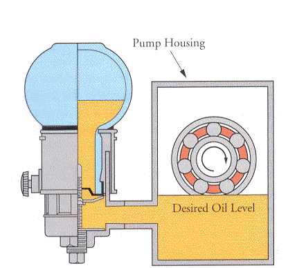
Figure 3: Pressure non-balanced constant level lubricator (Source: Trico Mfg. Corp.)
Again, bearing distress is inevitable if a constant level lubricator fails to maintain the desired oil level. An incorrect level setting can be caused by a number of factors. It will be clear from Figure 3 above that even small increases in the bearing housing-internal pressure can heighten the failure risk. Suppose there is heat generation and because of the addition of bearing protector seals the air no longer escapes and there’s a lack of housing-internal pressure balance. Perhaps the reasons why Worthington had included housing-internal balance holes in have been forgotten. The result may well be that the housing-internal pressure goes up or is unequal. As the housing-internal pressure rises ever so slightly, it will exceed the ambient pressure to which the oil level at the wing nut or slanted tube in the bulb holder portion of the constant level lubricator is exposed. According to the most basic laws of physics, a pressure increase in the bearing housing causes the oil level near the bottom of the bearing inner ring shoulder (Figures 3 and 4) to be pushed down. Lubricant will no longer reach the bearing’s rolling elements; oil turns black, and the bearing will fail quickly and seemingly randomly.
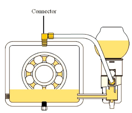
Fig.4: Pressure-balanced constant level lubricator. Be sure a large dia. balance line is installed. (Source: Trico Mfg. Co, Pewaukee, WI)
To re-state: At DN > 6,000 and to satisfy minimum requirements in a reliability-focused plant environment, a stainless steel flinger disc fastened to the shaft will often perform well. Such a disc will be far less prone to cause unforeseen outages than many other presently favored methods. Remember that traditional oil rings will abrade and slow down if they contact a housing-internal surface. Oil rings are sensitive to horizontality, oil viscosity, oil immersion, ring concentricity and RMS surface roughness.
If one upgrades to flinger discs, one accepts the findings of the legacy manufacturer whose advertisement is illustrated in Figure 2. That legacy manufacturer’s findings were backed by facts. Still, it must be ascertained that flinger discs are used within their applicable peripheral velocity so as to contact the oil and fling it into the bearing housing. The flinger disc O.D. must exceed the outside diameter of the thrust bearing and this dimensional requirement strongly favors placing the outboard (thrust) bearing(s) in a separate cartridge. Providing such a cartridge will add to the cost of a pump, as will the cost of a well-designed flinger disc. However, in most cases, the incremental cost will be considerably less than what it would cost to repair a pump just once.
See more articles from Heinz Bloch.
References
- Bloch, Heinz P. and Allan Budris; “Pump User’s Handbook: Life Extension,” 4th Edition, (2014), Fairmont Publishing, Lilburn, GA, ISBN 0-88173-720-8
- Bloch, Heinz P.; “Pump Wisdom: Problem Solving for Operators and Specialists”; (2011), Wiley & Sons, Hoboken, NJ; ISBN 9-781118-04123-9
- Bloch, Heinz P.; “Petrochemical Machinery Insights,” (2016) Elsevier Publishing, Oxford, UK, and Cambridge, MA, ISBN 978-0-12-809272-9
Why Pumpsets Should Not Be Installed in “As-Shipped” Condition