Author: Richard Martinez, KSB Standard Alloys
Producing energy savings within an industrial plant is a high priority for plant management. Reliability engineers focus on extending the mean time between repairs (MTBR), but they may often overlook the potential energy savings that can be generated if a full engineering study is performed as part of their root cause failure analysis (RCFA). This is especially true with regard to pumps since they are peppered throughout many facilities. Hydraulic engineers use computational fluid dynamics (CFD) to adjust the hydraulic fit of a pump to extend the MTBR and to reduce the energy costs of operating the pump. Such measures can dramatically reduce the life-cycle cost (LCC) of a pump, which is the total cost of ownership for a piece of equipment.
WHERE THE PUMP OPERATES
Many plants have a “bad actor” list. These are the pumps that have a MTBR of less than one or possibly two years.
Many different solutions are offered by manufacturers and service providers—such as improved shaft stiffness, metallurgical upgrades or wear coatings—to deal with cavitation
or suction recirculation.
These offerings might increase the MTBR, but they will not truly solve the problem. The real first step should be to evaluate the actual pump operation or the standard operating
point of the pump with the certified performance test supplied with the pump. Often, two troubling situations are revealed:
• The plant operation has changed, and the standard operating point of the pump is no longer within the preferred operating region of the pump curve.
• The pump was never operated within the preferred operating region.
As published in API 610, the preferred operating region of the pump curve is where the pump was designed to operate. By operating in the preferred operating region, the pump vibration will be at the lowest level, increasing seal and bearing life and extending the MTBR. This region is where the best efficiency point (BEP) is. Simply stated, low
vibration and peak efficiency means lower maintenance and lower energy costs for that pump.
REPLACEMENT—NOT ALWAYS THE SOLUTION
Once the problem pump is identified as not having a good hydraulic fit with the standard operating point, some would say that a larger or smaller pump—depending on the findings—should be purchased. For example, if the pump is running to the right of the BEP, then more capacity or a larger pump is needed. If the pump is running to the left of the BEP, then less capacity or a smaller pump is needed. Often, this option is not viable since a new pump requires a capital project with a new driver, foundation, piping, instrumentation and other equipment.
Another solution offered by some companies is a hydraulic rerate that can improve the hydraulic fit. However, this often still falls short of the true need and will certainly not optimize the pump efficiency.
In many cases, the best solution is to match the pump’s BEP with the standard operating point. Th is can only be accomplished with a custom impeller design. These impellers can
be developed by using CFD technology to simulate the hydraulic performance while iterating through several “what if ” hydraulic layout scenarios. These simulations allow
for the validation of the pump performance without the cost and time delays associated with building prototypes and performing certified performance tests.
Caution must be advised on two specific topics. First, not all successful CFD simulations will yield a hydraulic layout that can be manufactured. The hydraulic engineer must
understand the manufacturing processes to ensure that the solution is feasible. Second, not all desired modifications can be met. Sometimes, the required hydraulic change falls outside the feasible realm. However, in this situation, the CFD analysis can be used to validate that truly no other solution exists for this piece of equipment. That vital information can then be presented to plant management to support and justify the replacement of a high-maintenance pump.
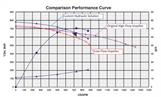
Pump performance comparison between high-flow, low-flow, and CHS impeller designs
STATE-OF-THE-ART TECHNOLOGY IN ACTION
A reliability engineer within a petrochemical refinery identified that his 3x4x13 OH2 pump was oversized and being operated to the left of the BEP. The BEP flow rate for the
pump was 1,200 gallons per minute (gpm), and the standard operating condition of the plant was 730 gpm. The pump had poor reliability with the original impeller and a MTBR of approximately 18 months. The typical vibration for this pump after a complete overhaul and being returned to the field was 0.25 inches per second.
Additionally, the pump efficiency was only 64 percent at this flow rate as opposed to the 76 percent efficiency at the BEP. The original equipment manufacturer (OEM) was contacted to see if it had a potential solution. The OEM had a low-flow impeller for this size and a type pump that had a BEP flow rate of 750 gpm, but the head was not sufficient to meet the system curve.
The facility tried to use the existing low-flow design and run with a two-pump operation to meet the system requirements. However, that solution meant that two pumps were
being operated to the left of the BEP. The plant returned to the original impeller and the one-pump operation. The engineer then began to look for a service provider that could offer a true, cost-effective solution to his oversized pump and reduce the maintenance costs, which were driving his LCC through the roof for this pump.
One of the independent service providers offered a unique approach to this problem by applying the analysis method described in this article. A careful evaluation of the
system curve and the overall pump design was performed. A CFD model was developed for the original impeller and the low-flow impeller. This would give critical information
to properly evaluate the suction neck and discharge volute characteristics relative to any new design. Several hydraulic layouts were developed and input into the CFD model to
see if an optimum design could be generated.
PROVEN RESULTS
It was determined that a new impeller could be designed to operate within the existing casing that would be a much better hydraulic fit. The CFD simulation indicated that,
with this new design, the new efficiency at the standard operating point would be 71 percent—almost an 11 percent increase in efficiency. Notice that the new BEP is five
points lower than the original design. This reduction in maximum efficiency is partially because of the new pumpspecific speed and also because of the losses associated with
the large throat area in the casing.
The new impeller was ordered and manufactured in conjunction with the next pump failure. A certified performance test was not required by the engineer based on the
results provided by the CFD simulation. It was agreed that the field instrumentation associated with this pump would generate sufficient data to validate the pump’s operation.
After startup, the pump capacity was as predicted. The vibration, which had a previous low reading of 0.25 inches per second, was only 0.05 inches per second. The amp load
on the motor coupled with the capacity also indicated that the 71 percent predicted efficiency was obtained within the accuracy of the field equipment. The higher efficiency generated an annual energy savings of more than $15,000 for this typical API process pump. This savings alone offered an eight-month return on investment of the new impeller. This pump is now off the bad actor list and the new MTBR is expected to be at least six years.
CONCLUSION
Pump efficiency matters. It is a clear indication of the off-design operation of the pump. Modifying the pump design to improve the efficiency can often generate enough savings
to justify the new design and the subsequent improved reliability of the pump. When evaluating a pump failure or the bad actor list, reliability engineers need to fully evaluate
where the pump is operating. They should also challenge the pump efficiency available to that hydraulic condition and not settle for what is traditionally supplied or what was
designed 10, 20, 30 or more years ago. The ability to generate accurate CFD models
makes these solutions feasible, timely and practical in today’s energy conscious world. P&S
See more from KSB!
ABOUT THE AUTHOR:
Richard E. Martinez is the managing director of Standard Alloys Incorporated in Port Arthur, Texas. He began his career in 1983 as a plant engineer within the energy industry. After several years, he was promoted to the Central Engineering Group’s Reliability department. In 1989, he joined Standard Alloys as head of the Engineering department where he was responsible for research and development of manufacturing processes and part design, hydraulic re-rate design of centrifugal pumps and design/manufacturing of replacement parts. In 2005, he became vice president of Operations, and in 2012, he assumed his current role.
*Originally printed in Pumps & Systems magazine September 2013 issue.