When you are selecting a submersible wastewater pump to meet your application needs, a pump system curve is a “must-have”. Whether you are selecting a sump pump for a new installation or replacing a failing sump pump, developing a curve for the desired performance can save you time & money with improved operational efficiencies. In this article, Industrial Flow Solutions™ shows you how to easily create a pump system curve.
Pump System Curve Key Data Points
We will use the example below to develop the pump system curve.
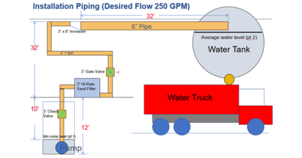
- Desired flow rate: 250 gallons per minute (GPM)
- Total elevation: 42’
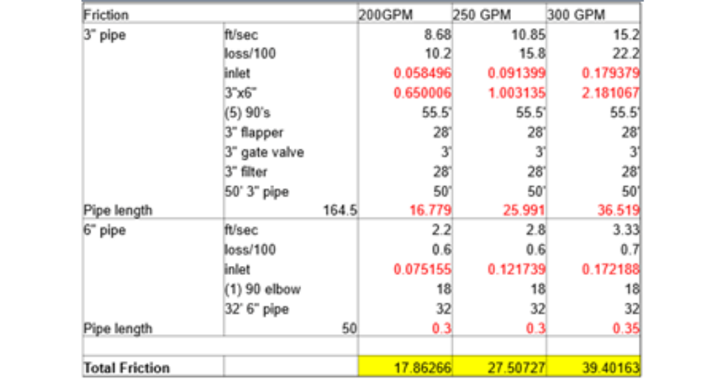
- Total length of 3” PVC pipe: 50’ with:
- (5) 90° 3” elbows
- 3” flapper check valve
- 3” gate valve
- Includes a 3” high-rate sand filter
- Includes a 3”x 6” PVC pipe increaser
- Total length of 6” PVC pipe: 32’ with:
- 90° 6” elbow
- Includes 6” inlet to water tank
Step 1: Calculating Total Dynamic Head (TDH) for Submersible Wastewater Pumps
TDH is the combination of the static lift (the elevation difference between the water level and the end of the pump discharge piping) and friction loss through the piping system. The formula is:
Total Dynamic Head = Pressure Head + Static Head + Velocity Head + Friction Head
- Pressure Head is the discharge pressure the pump creates, also referred to as “centrifugal pump energy”. In our example, pressure head = 0 as it is atmospheric pressure only.
- Total Static Head is the elevation difference between the liquid level in the tank you are pumping from to the elevation of the water in the discharge tank or pipe, and is 42’ in our example
- Velocity Head is the motion of the water expressed in terms of the head required to produce that velocity. The formula to convert the energy to head in feet is
Velocity Head = Velocity2/2G
In our example the velocity of the water through the 6” pipe is 2.8’ per second. “G” refers to the gravitational constant which is 32.2 ft/sec2. Expressed in the formula, it’s (2.8ft/sec)2/(2×32.2ft/sec2) = .12’ for the velocity head.
- Friction Head loss is the pressure loss caused by components of the system (i.e. pipe material, distance, etc.). The result is that you need more energy to move the water all the way through the system. The formula to calculate the friction loss is
Friction Loss = Friction Factor * Velocity2/2G
You need to calculate friction loss through every flow transition from fitting to fitting. The table below includes the data needed to calculate the friction loss at 200 GPM, 250 GPM, and 300 GPM.
With all of the values calculated, here is our completed TDH formula:
0 + 42’ + 0.12’ + 27.5’ = 69.62′ TDH (Rounded up to 70’)
Following the same formulas for 200 GPM and 300 GPM, you can determine additional points on the system curve.
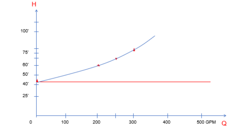
- 0 GPM: 42′
- 200 GPM: 60′
- 250 GPM: 70′
- 300 GPM: 82′
Step 2: Develop the Pump System Curve
With the calculated points, you can now develop the pump system curve.
- X axis shows Gallons per Minute (GPM)
- Y axis shows Head (in feet). Plot the points above starting with static head at 42’. Add the remaining point to arrive at the curve below:
Using Your Created System Curve
Given the desired flow rate of 250 GPM and the corresponding TDH of 70’, you can check the system curve against the performance curves of potential submersible waste pumps to determine which is best for your application.
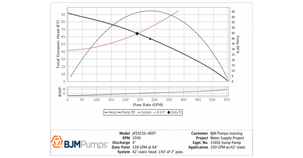
Based on the curve, we recommend BJM Pumps® 7.5HP JX55CSS Stainless Steel submersible pump because it provides 238 GPM at 64’ TDH, operating nearest the best efficiency point (BEP).
The curves are an important aspect and will get you close to what you need for a pump, but there are additional variables that may influence the specific pump you need. For additional considerations and information, contact IFS.
Industrial Flow Solutions™ offers a comprehensive portfolio of submersible pumps, direct in-line pumps and control solutions ideal for industrial, commercial, and municipal applications. IFS products are problem-solving solutions for Industries including Mining & Materials, Food & Beverage, Construction, Commercial Buildings, Municipal Water & Wastewater, and Power Generation & Utilities. With BJM Pumps®, Clearwater Controls, Stancor® Pumps & Controls, and OverWatch® Direct In-Line Pump System, IFS is turning flow problems, into flow solutions.
Contact one of the IFS Application Engineers today to learn more. 860-631-3618 | flowsolutions.com