Author: Heinz P. Bloch, P.E.
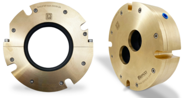
Bearing manufacturers with research and development capabilities frequently and timely respond to users’ needs by developing retrofit kits. These tend to incorporate improved bearing geometries or advanced materials technologies that include ceramic (“hybrid”) bearings. The 40-degree/15-degree matched set of Fig. 1 was developed for that reason; it most certainly solved a problem which the pump manufacturer and user were unable to solve without the bearing manufacturer’s help.
Another of many retrofit developments is highlighted in the two slightly different double row angular contact bearings of Fig. 2. In the event of high shaft loading from right-to-left, the mounting method depicted in the top sketch will prove more secure than that using a bearing snap ring in the lower portion of Fig. 3 (Ref. 1). Experience shows the remaining land at the bearing snap ring groove to be narrow and, potentially, too weak to restrain high imposed axial shaft loads.
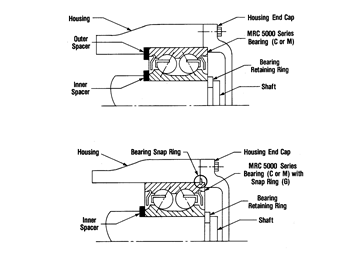
Fig. 3: Double-row angular contact bearing retained and located with spacer and step in bearing housing (top) vs. snap ring secured in bearing outer ring groove and held in place by housing end cap (bottom). The inner rings of these bearings will have to be mounted with a shaft interference fit of approximately 0.0005-0.0007 inches (12-17 micron)
Double-row angular contact bearings with two separate inner rings are available. Note, however, that their use would require applying a clamping torque (threaded shaft end and provision of a castellated clamping nut) to keep the bearing properly assembled.
Bearing cages
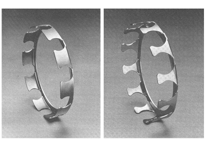
Fig. 4: Snap-in pressed steel cages for Conrad-type bearings (left) and filling slot bearings (right)
Bearing cages are needed to keep rolling elements equidistant from each other. The four configurations illustrated in Figures 4 and 5 are but a small sample of the many geometries and materials available for ball bearing cages. Although discouraged by API-610, steel cages are occasionally found in process pumps. Steel cages are generally less forgiving than machined brass cages. In fact, whenever rivets are used to keep together the mirror-image halves of certain pressed steel bearing cages (see Figure 6), the rivet heads are considered a weak link. Should they pop off, massive failure will often result.
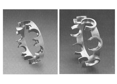
Fig. 5: Snap-in polyamide cage (left) and machined brass cage (right), both for Conrad-type bearings
Machined brass cages are considered more tolerant of minor installation defects and lubrication deficiencies. But they are not immune to damage should such deficiencies arise. Machined brass cages may respond poorly to situations where skidding is involved.
For years, it had been argued that permitting polyamide cages in process pumps would be out of tune with the safety and reliability improvement goals professed by many users. But modern polyamide cages include Nylon 46 and 66, Kevlar and L-PPS (Linear-Poly-Phenylene Sulfide). L-PPS has excellent thermal and chemical performance and has been installed for years in Japanese process pumps. Based on these experiences and as long as proper workmanship and tools are employed, these cages absolutely qualify for process pumps.
However, they are not recommended for process pumps at facilities with lax installation tools, or at plants that tolerate indifference towards the special needs of bearings with plastic cages. With plastic cages one cannot allow working temperatures at assembly (or during repair) to exceed the temperatures at which certain polyamides tend to soften. Also, certain types of wear and progressive polyamide cage degradation are not being picked up by low to moderate cost means of vibration detection, usually employing a portable data collector-analyzer or data terminal. In contrast, degradation of machined brass cages shows up more readily on these portable devices during predictive maintenance assessments on process pumps.
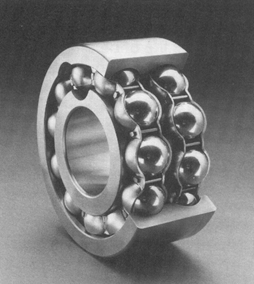
Fig. 6: Filling slot bearing (double-row style) with “stay-rod” cages
Note the different number of ball pockets in the snap-in steel cage for Conrad-type (deep groove) bearings (Fig. 4, left) and a snap-in steel cage for filling slot bearings (Fig. 4, right). Because an additional ball can be accommodated through the filling slots shown in Fig. 6, such bearings will have radial load capacities approximately 10-15% greater than those of otherwise dimensionally equivalent Conrad bearings.
However, filling slots greatly diminish axial load capacity; also, bearing balls rolling over the edge of a filling slot may cause vibration or interruptions in the desired continuous oil film. Because of those risks and much adverse experience, filling slot bearings are not acceptable for process pumps in modern plants.
Bearing preload and clearance effects
Bearing balls and raceways always deform slightly under load. Each bearing type or style or size has its own behavior when loaded. Suppose loading the shaft axially from left-to-right and looking at shaft movement relative to the housing end cap would result in the shaft end moving 0.001 inch (25 micron) to the right. In that case, the right-side row of bearing balls might no longer contact its inner ring raceway and would tend to skid. Skid situations wreck bearings and must be avoided, as explained in the earlier narrative dealing with upgrading and retrofit opportunities.
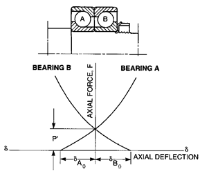
Fig. 7: Axial deflection is a function of bearing geometry and force acting on a bearing. Note castellated nut and tab washer, top half of illustration (Ref.1)
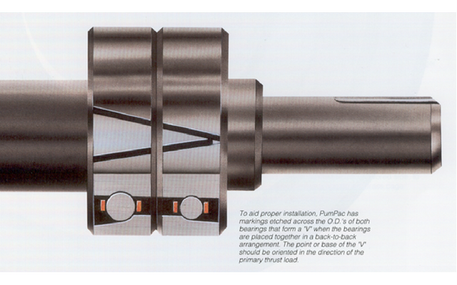
Preloading can avoid skidding and extend bearing life. Excessive clearance shortens bearing life. If the thrust loads acting on bearing “A” and bearing “B” are different and/or if skidding is to be avoided, it might be best to select bearings with non-equal load angles. However, the load angles in Fig. 7 are the same. Also, the plot shows a positive axial force P’. This indicates that the manufacturer of this particular matched set of bearings designed and manufactured each of the two inner rings a very small amount narrower (perhaps 0.0002 inches–5 micron) than the two outer rings. The two inner rings will make contact only after the castellated (cog-type) shaft nut has been tightened. When properly tightened the 0.0004 inch (10 micron) clearance will have been reduced to face-to-face contact with no clearance. The preload P’ exists before an operating load is superimposed.
Bearing dimensions and mounting tolerances
There are important differences in bearing-internal design clearances, manufacturing tolerances, and bearing mounting tolerances. Many of these are thoroughly explained in bearing manufacturers’ tables, listings and other literature. Internal clearances and other highly pertinent information is then coded as identification numbers and letters—“alphanumerics.” Bearing numeric codes are standardized and contain four digits, e.g., 7214. The first two digits refer to style and 72 would indicate an angular contact ball bearing. Multiplying the second two digits by a factor of 5 gives the nominal bore dimension, in this instance 14×5 = 70 mm. On precision bearings the four-digit number is always followed by suffixes.
Bearing alphanumerics without a suffix are a sure indication of inexpensive commodity bearings. Such bearings are cheap initially and their cost advantage is short-lived. They are prone to cause reliability issues in modern process pumps. The various suffixes generally differ among manufacturers and some suffixes can be very important. Not only would a complete listing of all available suffixes fill dozens of pages but these would have to be periodically updated.
As an example, the designation suffixes used in 2010 to identify certain features of SKF double row angular contact ball bearings are explained in Table 1, below. From our earlier discussion, double-row ball bearings with the suffix “D” would require a threaded shaft end, bearings with the suffix “E” would be disallowed, the bearing fit should be C3 for process pumps, and so forth. This small example illustrates why one must pay attention to suffixes.
Again, whenever alphanumeric suffix information is disregarded by the pump user, failure risks increase and calamitous consequences become much more probable. Unless you have in-house expertise, consider linking up with the application engineering group of a highly knowledgeable bearing manufacturer.
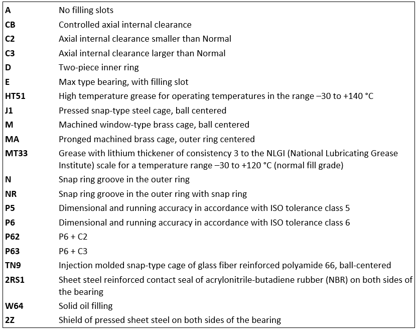
Table 1: Supplementary designations (suffixes) for SKF double-row angular contact ball bearings
There is no substitute for solid workmanship and conformance to the size and tolerance stipulations of competent bearing manufacturers. Only if there is no access to guidance from a competent manufacturer might one apply standard requirements to process pump bearings (in the 45 to 80 mm size ranges): If used in the location normally associated with the term radial, such bearings should have interference fits ranging from 0.0003 to 0.0007 inches (7 to 17 micron). Yet, because both shaft and bearing producers make their respective products with manufacturing tolerances, situations might arise where the shaft is near its high tolerance limit and the bearing is at its low tolerance limit. In that case, the resulting interference fit would greatly exceed 0.0007 inches and the bearing might be severely preloaded. Severe preloads create heat and reduce bearing life. To avoid excessive interference fits, the mating parts (shaft and bearing bore) must each be carefully measured at assembly. That kind of measuring takes time and only the true Best-of-Class (BoC) pump users have institutionalized these measurement routines.
Paying close attention to bearing mounting and tolerance dimensions is even more critical on the thrust bearing side of process pumps. If the bearing manufacturer supplied back-to-back mounted angular contact bearings that are flush-ground and thus have no preload, the mounting tolerance band would be the same as for radial bearings. If, however, these back-to-back bearings have a small gap between the inner rings and will thus become preloaded upon torque being applied to the shaft nut. An interference fit greater than 0.0003 inches (7-8 micron) should therefore be avoided.
In back-to-back bearings with a small gap between the two inner rings, having greater than 0.0003 inches (7-8 micron) of shaft-to-bearing inner ring interference would put radial preload on top of axial preload. For such a bearing (i.e., the one with operating load superimposed on excessive preload) to survive would require oil application method, lubricant properties and other parameters near perfection. This near-perfection may be an unrealistic expectation in most situations.
Our generalized dimensional recommendations pertain to typical alloy steel shaft materials. It should be noted that certain stainless steels have higher coefficients of thermal expansion than AISI 4140 and similar alloy steel. For stainless steel shafts the stipulated typical interference fits may have to be relaxed by a few percent. In all instances, outer ring installation and assembly tolerances should be loose fits ranging from 0.0002-0.0012 inches (5-30 micron). Again, it is worth recalling that the bearing manufacturer will produce outer ring outside diameters within a given tolerance band. Accurately measuring the difference between housing bore and bearing outside diameter may be difficult. Electronic or air-gauge measurements may be feasible and plug gauges are another possible option. We are cautioning against entrusting bearing-related pump repairs to an unskilled work force.
The above are just a very small part of many “form tolerance issues” for bearings and shafts; form tolerances include perpendicularity of shoulders, concentricity and out-of-roundness of cylindrical or tapered surfaces, etc. But form tolerances are a complex subject that takes time to master. Selection and execution of the proper shaft and housing fit is just one part of making sure a bearing runs properly.
Shoulder run-out is typically held to a 0.0003 inch (7-8 micron) maximum and shaft straightness deviations should typically not be allowed to exceed 0.001 inch (25 micron). If, on the other hand, we were to make use of every bit of the bearing manufacturer’s application engineering knowhow, we would save much money. Of course, the manufacturer with this knowhow would have to charge 10 or 20% more for their bearings than the bearing manufacturer who plays games by selling low and repeatedly. Rest assured that ascertaining sound practices and making full use of the capabilities of top notch manufacturers makes economic sense. If you made a competent manufacturer your technology resource and training provider, your plant would benefit immensely. Applying knowledge will result in long-lasting, reliable pumps. “Again, Knowledge is Uptime” whereas repeat failures drain your resources and deprive you of safe operations (Ref. 3).
Reference
- Bloch, Heinz P. and Allan Budris; “Pump User’s Handbook: Life Extension,” 4th Edition, (2014), Fairmont Publishing, Lilburn, GA, ISBN 0-88173-720-8
- Bloch, Heinz P.; “Pump Wisdom: Problem Solving for Operators and Specialists”; (2011), Wiley & Sons, Hoboken, NJ; ISBN 9-781118-04123-9
- Bloch, Heinz P.; “Petrochemical Machinery Insights,” (2016) Elsevier Publishing, Oxford, UK, and Cambridge, MA, ISBN 978-0-12-809272-9