Introduction
Mechanical seals can be designed in different arrangements and orientations. This gives the seal OEM and end-user options when selecting the correct seal design for a specific application. Seals can be provided as an Arrangement 1 (single seal), Arrangement 2 (dual unpressurized seal), and Arrangement 3 seals (dual pressurized seal). While each of these options has a large installed bases in the field, the unique characteristics of each arrangement may make one more appropriate for a specific service.
 Arrangement 2 seals consist of two mechanical seals where the cavity between the inner and outer seal is maintained at a pressure lower than the pressure in the seal chamber. The implies that the inner seal will operate with process fluid in the film between the seal faces and this process leakage will enter the cavity between the seals. This secondary collection cavity is one of the primary benefits of an Arrangement 2 seal. The process fluid in this cavity can be collected and disposed of in a manner which reduces process emissions to the environment.
There are two main design options for Arrangement 2 seals. These options determine if the cavity between the seals is filled with a liquid or a gas and are often referenced by the API 682 configuration codes. A 2CW-CW defines an Arrangement 2 seal with a liquid buffer fluid in the cavity between the seals. A 2CW-CS defines an Arrangement 2 seal with a gas or process vapors between the seals. The initial selection of one of these options is critical and impacts the seal design, piping plans, supporting utilities and disposal requirements.
 2CW-CW: dual seal with a liquid buffer fluid
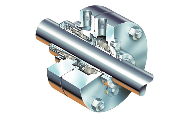
A 2CW-CW seal uses two liquid mechanical seals arranged in a face-to-back orientation. The cavity between the seals is filled with a buffer fluid which provides a suitable environment for the outer seal and collects process leakage from the inner seal. In most cases, the inner and outer seals are of a similar design and have the same operating capabilities. This allows the outer seal to serve as a true back-up or redundant seal to the inner seal.
Pros
There is a misconception that an Arrangement 2 seal only serves as a redundant sealing design. There are several other functional benefits for a 2CW-CW that may make it the best selection for a specific application.
- Redundant seal – In the case of a failure of the inner seal, the outer seal can contain the process fluid and allow for an orderly shutdown of the pump
- Capture leakage – Process leakage (during normal operation or in the case of an inner seal failure) is captured in the buffer fluid and can be disposed of in an acceptable manner
- Minimize atmospheric emissions – Process leakage is captured without significant emission to the environment
- Improve the environment at inner seal – Buffer fluid can provide additional cooling to the inner seal which can improve seal reliability
- Prevent coking or solidification of process leakage – The barrier fluid can help prevent the process fluid leakage from coking, crystallizing, dehydrating or solidifying by eliminating direct exposure to the atmosphere
- Monitor the inner and outer seal leakage – Monitoring the buffer fluid level in the reservoir can provide an indication of the seal condition and performance
- Modified LDAR – Using a dual seal with the buffer cavity vented to a collection or disposal system may reduce the required monitoring frequency on LDAR programs
Considerations
While migrating from a single seal to a dual seal certainly provides benefits to the end-user, the solution requires additional space and auxiliary equipment.
- Larger space required – A dual seal physically requires more space in the seal chamber and adjacent area of the pump
- Use of a buffer fluid – Requires a buffer fluid suitable for application conditions and compatible with the process fluid
- Contamination and changing of the buffer fluid – The buffer fluid may become contaminated over time and require draining and refilling to obtain maximum reliability
- Adding or draining buffer fluid in operation – Buffer fluid levels may need to be adjusted while the pump is in operation
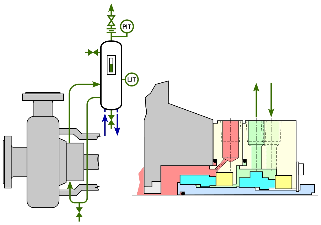
- Piping plan 52 – A 2CW-CW seal will use a Piping Plan 52 which requires the use of a reservoir, interconnecting piping, and instrumentation
- Use of utilities – Many reservoirs will benefit from cooling to control fluid temperatures and will require connections to the plant’s cooling water system
- Connection to a flare or recovery system – The reservoir is intended to be connected to a flare or recovery system to allow for controlled disposal of process fluid leakage
 2CW-CS: dual seal with a containment seal
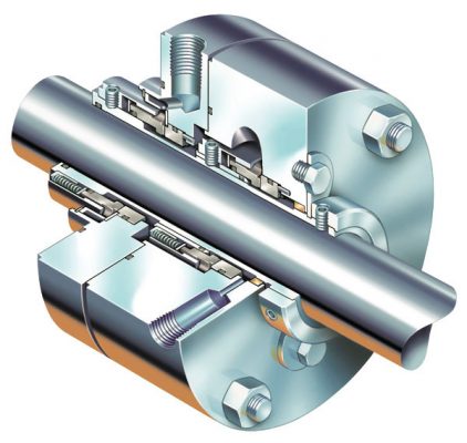
Seal OEMs have designed seals which can operate effectively with no liquid between the faces. One seal design which uses this strategy is an Arrangement 2 seal where the outer seal is a dry-running containment seal. The term “containment seal” has a specific definition in that it is intended to run on process vapors or an inert buffer gas. It is intended to operate at low pressures (less than 10 PSI or 0,7 bar) for most of the seal’s operating life. In case of an inner seal failure, the containment seal is intended to operate at process conditions for a minimum of eight hours to allow for an orderly shut-down of the pump.
The containment seal cavity (between the inner and outer seal) will be exposed to process leakage. This leakage may be in the form of vapors, liquids, or mixed phase process. The containment seal cavity will be vented or drained to prevent the build-up of process leakage and allow for proper collection or disposal. An Arrangement 2, 2CW-CS is a popular selection in applications where the process fluid is clean and fully vaporizes in the containment seal cavity. In addition to disposal, an external buffer gas (normally nitrogen) may be introduced into the cavity to sweep away the process leakage, protect the containment seal, and reduce process emissions to the atmosphere.
Pros
Arrangement 2 seals with a containment seal offer many of the same benefits as a dual liquid seal and a few additional features unique to this design.
- Redundant seal – In the case of a failure of the inner seal, the outer seal can contain the process fluid and allow for an orderly shutdown of the pump
- Capture leakage – Process leakage (during normal operation or in the case of an inner seal failure) is captured in the containment cavity and can be disposed of in an acceptable manner
- Minimize atmospheric emissions – Leakage is captured without significant emission to the environment
- No buffer fluid or reservoir required – Eliminating the need for a buffer liquid makes this design specifically favored for remote locations or areas with limited maintenance personnel
- No utilities required – There are no needs for cooling water since there is no buffer fluid or additional cooling required by the seal
- Monitor the inner leakage – The inner seal leakage is monitored by pressure or level in the associated piping plan
- Modified LDAR – Using a dual seal with the containment seal cavity connected to a collection or disposal system may reduce the required monitoring frequency on LDAR programs
Considerations
- Larger space required – A dual seal physically requires more space in the seal chamber and adjacent area of the pump
- May use a buffer fluid gas – Some applications may benefit from the use of a nitrogen buffer gas injected into the containment seal cavity
- May require a gas control panel for buffer supply – If a buffer gas is used, a gas control panel is required to properly condition, monitor, and control the gas injection
- Requires a disposal system for liquids and/or vapors – A different leakage disposal system is required for gas phase leakage than for liquid/mixed-phase leakage
- Connection to a flare or recovery system – The containment seal cavity is connected to a flare or recovery system to allow for controlled disposal of process gas and/or liquid phase leakage
- Monitor the outer seal condition – The containment seal is operated at a low pressure and there is a limited ability to test the seal condition while in operation
Piping Plans
Piping plans are standardized strategies which improve the operating characteristics and reliability of a mechanical seal. Arrangement 2 seals will require a piping plan (or plans) specific to the seal design and the nature of the process leakage.
- Piping Plan 52 – Plan 52s are used to store, condition, and monitor the buffer fluid in a 2CW-CW seal application. The reservoir will be connected to a recovery or disposal system and may require cooling water to regulate buffer fluid temperatures.
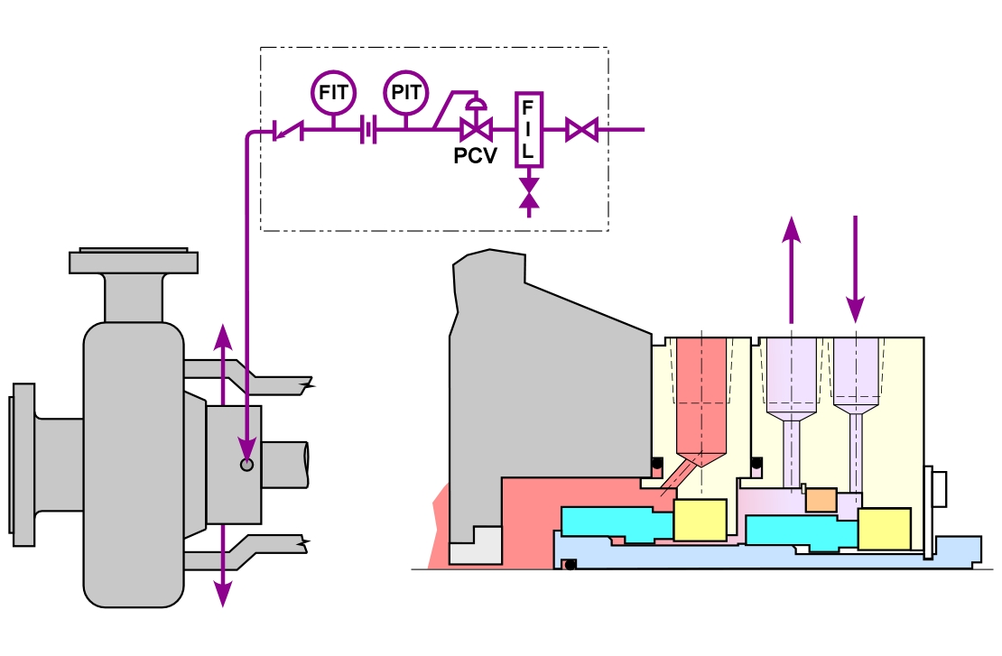
- Piping Plan 72 – A Plan 72 provides a flush of an inert buffer gas into the containment seal cavity of a 2CW-CS seal. The control panel helps control and monitor the flow of gas into this system
Piping Plan 75
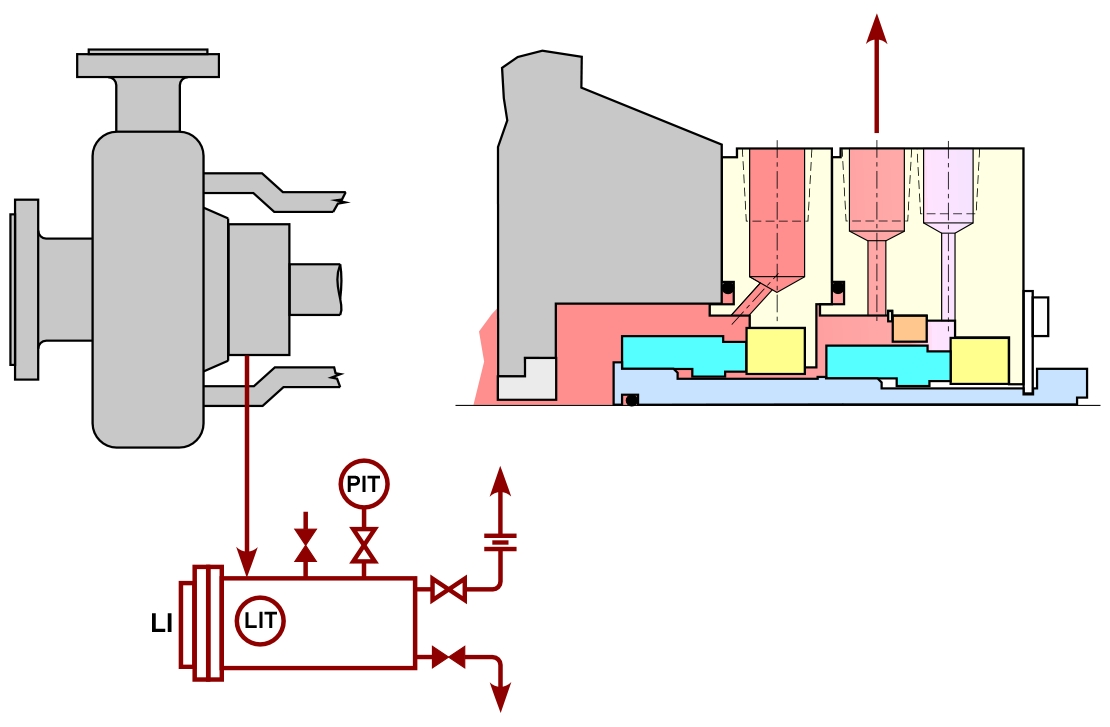
- Piping Plan 75 – Liquid or mixed phase leakage into a containment seal cavity if piped to a collection vessel. This vessel is used to collect, monitor, and dispose of process leakage.
Piping Plan 76
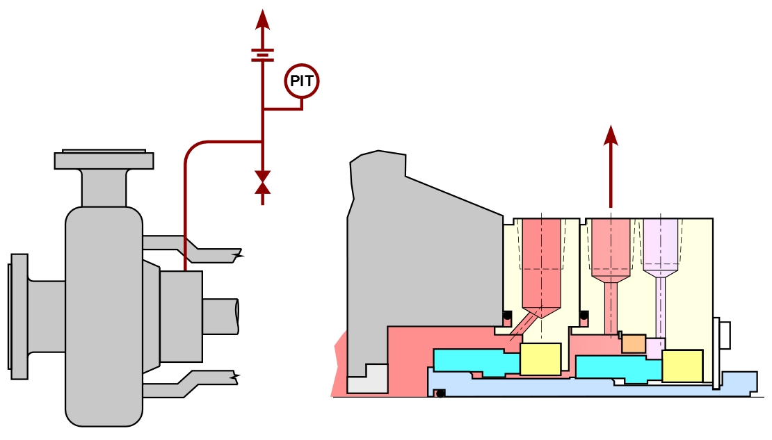
- Piping Plan 76 – Process liquids which fully vaporize are connected through piping into a flare or recovery system. This piping is instrumented to monitor seal inner seal performance and alarm on a seal failure.
Conclusions
Arrangement 2 seals offer significant benefits to end-users and can help them achieve their reliability and emissions goals. Understanding the seal design and appropriate piping plan is key to selecting the correct seal for a specific application.