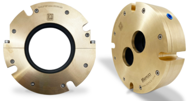
Perhaps half of the world’s oil-lubricated industrial pump bearing housings are furnished with inexpensive oil rings, also called “slinger rings,” that lift the lubricant from an oil sump (Figs. 1 and 2). In some applications, oil rings or small discs that just barely contact the oil at its level surface are helpful for maintaining the oil volume more uniformly mixed, i.e., to prevent temperature stratification. Stratification is a term that describes hot oil floating upward and staying near the top of the oil sump. Conversely, the cooler oil has greater density and tends to sink down to the bottom of a bearing housing.
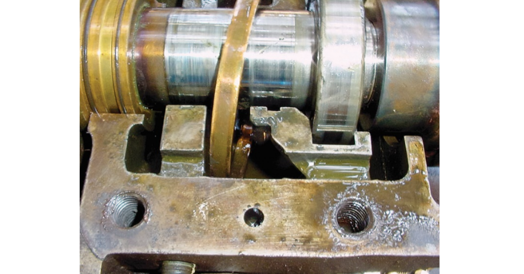
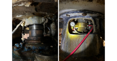
Fig. 2: An unrestrained oil ring likely to move uncontrolled is likely to abrade
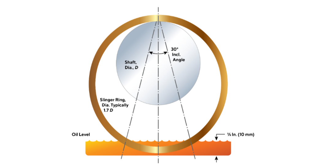
Typically, the loose oil rings shown in Figs. 1 and 2 are immersed about 3/8th inch (~10-11 mm) for the purpose of spraying oil into the bearings. Oil rings are not required in pumps with low-to-moderate shaft peripheral velocities. In these typical “without oil ring” designs, the oil level must reach to the center of the lowermost bearing element—usually a bearing ball.
Bearing bore diameter and shaft velocity constraints define whether the pump should be designed for the oil to reach the center of the lowermost ball or roller. If these parameters are too large, most pumps will be provided with one or two loose oil rings that dip into the oil and spray it into the bearings.
Bearing peripheral velocities are more conveniently expressed as DN-values, the product of multiplying inches of shaft diameter times shaft rpm. For example, a 70 mm (~2.75 inch) bearing operating with a shaft turning at 1,800 rpm would have a DN-value of 4,960; values below 6,000 are somewhat arbitrarily considered low-to-moderate DN numbers. In designs with DN < 6,000 (conservative) and possibly reaching (but not exceeding) a DN as high as 8,000, both housing geometry and constant level lubricator height settings are generally selected to allow lubricating oil to reach the center of the lowermost bearing ball or rolling element. Keep the numbers 6,000 to 8,000 in mind; they represent an interesting DN parameter because the pump manufacturer sometimes exceeds even 8,000. Manufacturers get way with it because they operate their machines with perfect shaft alignment whereas the users’ shafts, if operating at a slight angle, allow these oil ring to contact the bearing housing, The oil rings then tend to slow down; they can even abrade.
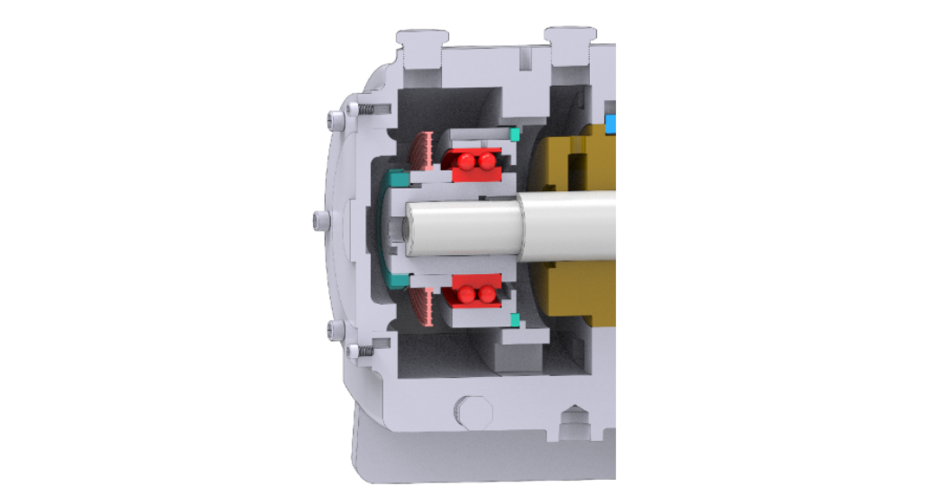
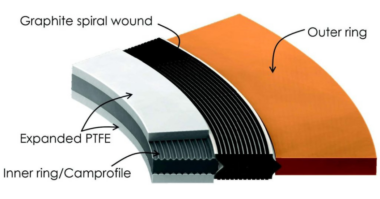
Fig. 3: The drawbacks of loose oil rings were widely known in the 1960s. At that time a prominent US pump manufacturer joined European pump makers in offering flinger discs, as shown in this bearing housing.
Satisfactory oil ring functioning is obtained in the range of from 2,000-2,500 ft/minute shaft surface velocity, which can also be expressed in terms of diameter and rpm. Some bearing manufacturers (and also machine designers) recalculate to show the acceptable range of surface velocities comply in the metric system. Bearing producers often use a dN expression, with “d” generally designating a mean, or average, diameter (mm) of rolling element bearings. The mean, or average dN would equate to [½] x [OD+ID] x rpm and we have seen dN-range stipulations from 300.000 to maximum values of 500,000. As an example, a bearing with a 100 mm bore, an OD of 180 mm, and a shaft operating at 3,000 rpm would have dN = ½ [100 + 180] X 3,000 = 420,000. The shaft surface velocity would be 100 x 3.14 x 3,000 = 942,000 mm/min or 3,090 ft/min.
Seeking reasonable agreement with the numbers given above, we looked up a 400 mm (~15.7-inch shaft diameter) double-row spherical roller bearing used in a large mixer-agitator drive. With grease lubrication, the manufacturer allows a maximum speed of 380 rpm; its DN would thus be (15.7) x (380) = 6,000. With oil lubrication, the bearing manufacturer advises a maximum speed of 480 rpm. Its DN would equal 7,540. The same bearing’s outside diameter is 650 mmm, its metric “d” is (650 + 400)/2 = 1,050/2 = 525 mm. Therefore, dN for grease would be (525) x (380) = 199,500; dN for oil = (525) x 480 = 252,000.
Our conclusion would be that this shaft and its bearing system approach the x and exceed the upper limits of shaft surface velocity. The equipment manufacturer tested the machine for a few hours at close to best achievable conditions of oil viscosity, shaft horizontality, ring immersion, etc. He acted in good faith when he shipped the machine to your plant. However, operating conditions at your plant are far from ideal, and the machine will likely experience an above-average number of failures. Perhaps it would have been prudent to upgrade the lubrication system at the specification stage, or to do so now, by identifying and scheduling a combined repair and upgrade task to be undertaken by a competent repair shop. My definition of a competent repair shop is one that subscribes to educating its customers and explains how these vulnerabilities can be circumvented.
Learn more about it from Reference 1: Bloch, Heinz P., “Optimized Equipment Lubrication, Oil Mist Technology and Full Standby Protection,” October 2021, DeGruyter Publishing, Berlin/Germany, ISBN 978-3-11-074934-2