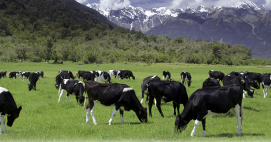
The Mackenzie Country or Mackenzie Basin is a wide valley between the mountain ranges of the Southern Alps, namely the Ben Ohau Range and the Rollesby and Delgaty Ranges in the center of New Zealand’s South Island. It is the largest area of this type in New Zealand and historically has been used for sheep farming. This has more recently changed to cattle farming and has also become a popular tourism destination. Lake Pukaki sits at the North End of the valley and is known as the most beautiful lake in New Zealand because of its amazing blue color. The average depth is 154 feet, (47 meters), and holds approximately 1,231,718,400,000 us gallons, (4,662,561,345,929 liters)
The Pukaki Irrigation scheme constructed between September 2017 and October 2018 delivers irrigation and stock water to approximately 14,826 acres, (6,000 hectares) over 4 high country stations in this region.
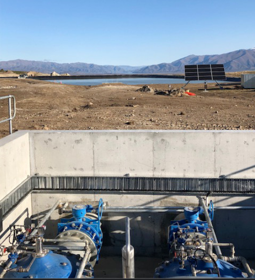
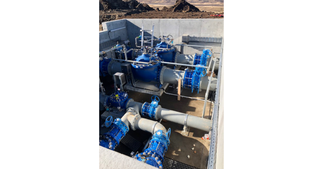
The project, necessary to supply the water for cattle and irrigation, included a siphon extracting water from the Genesis owned Tekapo stilling basin, 20 miles, (32 km) of piping ranging in sizes from 12” (DN 315) to 51” (DN 1300), 3 mainline Pressure Reducing Valve stations featuring Cla-Val Electronic Control Valves with Cla-Val VC-22D Controllers, Cla-Val X144 Flow Meters and Cla-Val X143 Series Power Generators. Ten property supplies with Cla-Val Series 93 Pressure Control Valves with X144 Series Flow measurement and a break pond controller using dual 24” (600 mm) Cla-Val 131 Series Electronic Level Control valves also featuring X144 flow measurement as well as 133 Series measurement and KO Anti-Cavitation trim.
Two 24” (DN600) electronically controlled dual solenoid operated valves with anti-cavitation trim, operating in parallel, will maintain a constant pond level by regulating the filling rate, accordingly, based on the pond’s current level and at the same time lowering the pressure to 177 psi (12.2 Bar).
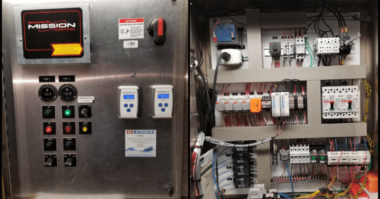
Two VC-22D electronic valve controllers, control the operation of the two 24” (600mm) dual solenoid control valves by sending electrical pulses to the opening solenoid, allowing water to flow out from the valve cover chamber, which in turn, allows the valve to open slightly with each pulse, or to the closing solenoid, allowing water to flow into the valve cover chamber, which in turn, allows the valve to close slightly with each pulse. The VC-22D uses a customized Valve App for the logic controls. This allows for complete control of the valve using intuitive programming screens, allowing for easy and fast programming. Complete capabilities allow either stand-alone operation or easy integration into the SCADA ststem. It works on the principle of modulating level control by position with the valves working in a single or dual valve operation. The controllers are interlocked so operation can be switched over periodically between the two valves. ASIA PACIFI
On automatic mode, the lead valve controller initiates the valves’ operation based on the current pond level. When within the pond level set point, the lead valve is in the close position with the lead valve controller sending a digital command to the standby controller to keep the standby valve close. As the pond level drops below the level set point, the lead valve is actuated by the controller to open and modulate to the specified target position. The target position is determined by a level versus position control curve programmed into the Valve App.
If the pond level continues to drop and the target position reaches a pre-set switch high position set point, the operation switches from single to dual valves, with the lead valve controller removing the digital command to the standby controller, allowing the standby valve to open and modulate to the specified target position. The lead valve then modulates to control at the same target position as the standby valve.
As the pond level rises and the target position reaches a pre-set switch low position set point, the operation switches back to single, with the lead valve controller sending a digital command to the standby controller to close the valve and keep it close and the lead valve modulating to control at the specified target position.
The valve closes as the pond level reaches the pre-set level set point.
A manual mode is also available on both controllers, wherein you can set the position you want the valve to modulate to. This mode is suited for initial pond filling, to keep the valves from working continuously at or near its pre-determined maximum velocity.
In the event of a loss of pond level feedback, an action is programmed to slowly close the valve or valves. Further, a high (overflow) level switch sends a signal to SCADA, which then sends a digital signal to the VC-22D controller to close the valve or valves.
If the flow rate goes above a pre-determined flow, an action is programmed to keep the opening solenoid from pulsing but allows the closing solenoid to operate as normal. This is to limit the flow velocity across the valve during peak operation.