Stage 2 – Application of Smart Valve Technology on large diameter pipelines for Pressure Control
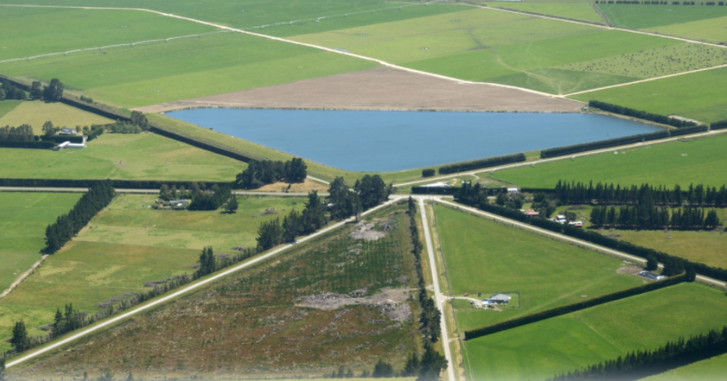
Stage Two of Central Plains Water located in the South Island of New Zealand was completed in 2018.
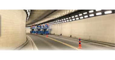
Located between the Selwyn and Waimakariri Rivers it supplies pressurized water to 20,000 hectares via a 23km long 2.5m GRP supply pipe and around 200km of supply piping.
After the success of Stage One scheme which featured over 400 Cla-Val Control Valves including 5 x 750 and 4 x 600 valves Cla-Val was again chosen to be the supplier of all automatic control valves.
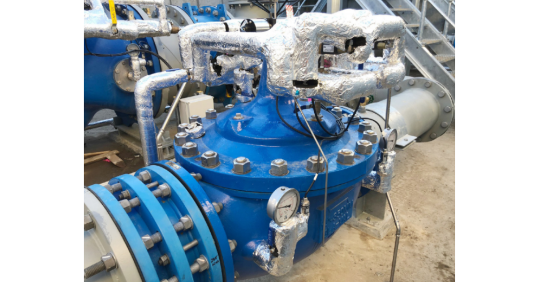
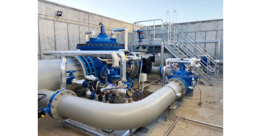
The three main lines being DN1200 are all controlled via Cla-Val’s latest generation smart valves.
A DN900 and DN350 electronically controlled dual solenoid operated valve, configured to work as a main and jockey PRVs respectively, maintains a constant downstream pressure or modulates to a pre-determined position set point.
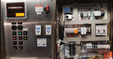
A VC-22D electronic valve controller, controls the operation of the 900mm and 350mm dual solenoid control valves by sending electrical pulses to the opening solenoid, allowing water to flow out from the valve cover chamber, which in turn, allows the valve to open slightly with each pulse, or to the closing solenoid, allowing water to flow into the valve cover chamber, which in turn, allows the valve to close slightly with each pulse. The VC-22D uses a customized ValvApp for the logic controls.
Both main and jockey VC-22D controllers are interfaced to the customer supplied RTU, via Modbus, to provide the required mode of operations and monitor the valve’s position, upstream and downstream pressure and the flow rate across the valve. Using a program integrated on the ValvApp, data gathered from the valve position, upstream and downstream pressure transmitters are assimilated into a proprietary algorithm program, that’s based on valve size and configuration, to arrive at a flow measurement.
Each PRV stations has three operating states, AUTOMATIC, HYDRAULIC and STATION OFF, which the operator can either set locally or remotely, via SCADA, to operate the PRVs.
When in AUTOMATIC state, the RTU selects which valve will control and maintain the downstream pressure or modulate to a certain position, while holding the other valve either in close or current position. Certain conditions, programmed on the RTU, must be met for the RTU to command the PRVs to enter or depart from the different modes of operation, when in this state.
When commanded to ZERO-FLOW MODE, both jockey and main PRVs remains at the fully close position (0% open).
If, while in the ZERO-FLOW MODE, the downstream pressure drops below 95% of the pre-determined pressure set point, entered locally on both main and jockey PRV controllers, for a period of more than 60 seconds, the station enters to LOW FLOW MODE.
On LOW FLOW MODE, the jockey PRV is under pressure control and will modulate to maintain the downstream pressure within the pressure set point, while the main PRV is commanded to remain in the fully close position.
If, while on LOW FLOW MODE, the downstream pressure exceeds 105% of the pressure set point for a period of more than 60 seconds, the station departs from LOW FLOW MODE and enters into ZERO-FLOW MODE.
If, while on LOW FLOW MODE, the downstream pressure drop below 95% of the pressure set point or the jockey PRV flow is more than 220 l/s, for a period of more than 180 seconds, the station enters into HIGH FLOW MAIN CONTROL MODE.
On HIGH FLOW MAIN CONTROL MODE, the jockey PRV is commanded to hold its current position and the main PRV reverts to pressure control and begins to open. The main PRV modulates to maintain the downstream pressure within the pressure set point.
If, while on HIGH FLOW MAIN CONTROL MODE, the downstream pressure exceeds 105% of the pressure set point for a period of more than 120 seconds, the station departs from HIGH FLOW MAIN CONTROL MODE and enters into LOW FLOW MODE.
If, while on HIGH FLOW MAIN CONTROL MODE, the downstream pressure drop below 95% of the pressure set point, for a period of more than 180 seconds, the station enters into HIGH FLOW JOCKEY CONTROL MODE.
On HIGH FLOW JOCKEY CONTROL MODE, the main PRV is commanded to hold its current position and the jockey PRV reverts to pressure control and modulates to maintain the downstream pressure within the pressure set point.
If, while on HIGH FLOW JOCKEY CONTROL MODE, the downstream pressure exceeds 105% of the pressure set point for a period of more than 120 seconds, the station departs from HIGH FLOW JOCKEY CONTROL MODE and enters into HIGH FLOW MAIN CONTROL MODE.
A PIPE FILL MODE can be selected locally, via the HMI located at the PRV station, for initial pipeline filling. When selected, the jockey PRV will revert to position control, with SCADA remotely sending a position set point to the jockey PRV, and begins to open and modulates to within that position set point. The main PRV remains close.
The station remains on PIPE FILL MODE until the operator manually selects a different mode or if the downstream pressure is equal or above the RTU determined “minimum downstream pressure” for the given PRV station, the station automatically exits from PIPE FILL MODE and returns immediately to ZERO-FLOW MODE.
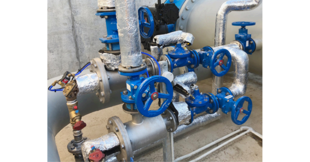
When in HYDRAULIC state, either by selection, loss of power or the unavailability of the RTU, the jockey and main PRVs will be under the control of the valves’ hydraulic pilot while the electronic pilot system are isolated. The main PRV hydraulic pilot set point is the same as the electronic pressure set point, entered on the VC-22D controller, while the jockey PRV is set 5 psi above the main PRV hydraulic pilot set point.
The hydraulic circuit is kept isolated by two 50mm hytrol valves held closed by an energized solenoid wired to an external relay, which can be actuated open or close with a SCADA command, and powered independently. Another 50mm hytrol (block) valve, installed between the cover and the electronic pilot system, is held open by an energized solenoid wired to an external relay, which can also be actuated open or close with a SCADA command, and powered independently. Once both solenoids are de-energized, either on power failure or with SCADA intervention, the hydraulic circuit is then released and the valves are under the hydraulic pilot control while the block valve will close and isolate the electronic pilot system.
Under HYDRAULIC state, both jockey and main PRV are able to open when the downstream pressure is below both PRVs’ hydraulic pilot set point. As flow increases and the downstream pressure drops below the jockey PRV set point, but above the main PRV set point, the jockey PRV will start to open and modulates to maintain the downstream pressure to within its set point, while the main PRV remains close. As flow increases and downstream pressure continuous to drop below the main PRV set point, the valve will start to open to allow for more flow downstream. As downstream pressure rises above the jockey and main PRV set point, the valves would start to close. On no flow conditions, both PRVs are close drip tight.
When in STATION OFF state, both main and jockey PRV go to position control with a remote set point of 0% sent by the RTU to both VC-22D to drive the valve/s to the fully close (0% open) position and hold there.
Once the station is in STATION OFF mode, it will remain in this mode until a different mode (AUTOMATIC or HYDRAULIC) is commanded.
Read Stage 1 – Application of large diameter PRV’s in parallel to control pressure in large diameter piping systems to learn more about this project.

Comments