Author: Ross Waters, President, CGIS
Most check valves are selected by size and Class to match the size and Class of the pipe. While this is convenient and simple, it is not necessarily the best way to choose the correct check valve. This article looks to examine the consequences of selecting check valves the way most currently are and offers a different method of selection, why it can lead to far higher and longer performance and the supporting formulas and fluid dynamics that one can use to prove it yourself.
There are several different types of check valves but all are required to prevent back flow; that is how their other name came about – “non-return valves” or NRVs. They do this largely independent of any external device or implement. Instead they rely primarily on the piping system’s internal factors like cessation of flow and flow reversal; some with assistance only from gravity and some with internal springs. Simply put; all check valves open by flow and close when flow stops.
Unlike other types of valves that are operated manually or by automation and are placed in their operating positions like fully open or fully closed; check valves require sufficient flow velocity to open fully and without knowing some basics like flowrate, pipe ID and specific volume; you cannot know if that condition exists by simply knowing the pipe size.
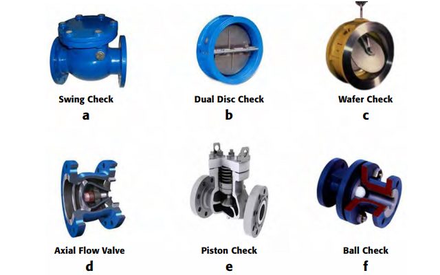
The six distinct types of check valves:
a. Swing Check (bonneted unassisted gravity swing check; generally RF flanged)
b. Dual Disc Check (dual flapper wafer check; generally wafer flanged)
c. Wafer Check (single flapper wafer check; generally wafer flanged)
d. Axial Flow (axial disc or centre-guided “non-slam” check; generally RF flanged)
e. Piston Check (piston check; generally RF flanged above 1” (25mm)
f. Ball Checks (also plug checks, generallyRF flanged, screwed or SW)
We shall focus on the most common of the check valves – the Swing Check. It is available in a very wide variety of sizes, pressure classes and materials. There are three basic variations as shown in examples a, b and c below.
a) Bonneted unassisted gravity swing check

b) Dual Disc Wafer Body

c) Single Flapper Wafer Body

All styles of check valve operate under the same principals. The traditional method of choosing a body size to match the pipe size will often lead to a valve that is not fully open at minimum or even normal flowrates. While this practice is widely used, in most cases this will not lead to best performance or the lowest cost of ownership.
The reason is similar for control valves. To obtain a properly sized control valve you must solve for the required Cv (sizing the valve or orifice); and once that is solved, (usually as Cv Min, Cv Norm and Cv Max) for the flowrates at the process’ minimum, normal and maximum flow conditions, you select the proper body size for the trim (internals) you have determined best suits those Cv values.
Cv, the flow coefficient of a device (in SI units it is the Kv flow factor) is a relative measure of its efficiency at permitting fluid flow. It describes the relationship between the energy (as pressure drop) across an orifice, valve or other piping component and the corresponding flowrate.
The installed Cv of any valve is the Cv that occurs when the valve is operating in the piping system and the process is running. The published Cv of any check valve is irrelevant if it isn’t fully opened. As most check valves offer one inlet and internal trim dimension per size and Class, the chances are low that it will match the application it will be installed in and without sizing, will only be apparent after installation when it may be too late.

The diagram above shows a typical bonneted unassisted gravity swing check with a normal flowrate of water at 7 ft/sec (2.2 m/sec) and a same pipe-sized venturi inlet single flapper wafer swing check under the same flow conditions.
The difference is that the flow is insufficient to fully open the gravity swing check and it fails to open enough to produce the Cv it is capable of. This also has a detrimental effect on the service life of the valve as it means the flapper will be unstable and moving constantly, subject to wear and tear; and a shorter life than could be expected if it were properly sized.
The single flapper wafer check takes the 7 ft/sec water and momentarily increases the velocity at the disc through a decrease in orifice size to lift the flapper fully, a position where it is stable and achieves the highest installed Cv. This requires an engineered and sized inlet orifice, what we call a Venturi inlet.
If we install line-sized check valves that have not been sized for low and normal flow conditions and they do not fully open the disc, we should expect shortened life. This is due to the mechanical movement of the disc as the flowrate varies, however slightly, during the valve’s service life and the turbulence and the vibration that result from it. If we installed properly sized check valves for minimum flow rates and obtain 100% Cv, then we will always achieve 100% Cv on the higher flowrates. Once fully open we should expect longer life through the flapper’s stable position – 100% open is 100% open.
In order to properly size a check valve, you must determine the minimum velocity required to fully lift the disc. Then find the mean velocity of flow in the piping system and ensure it is greater than or equal to the minimum required velocity.
Variables:
v = mean velocity of flow (ft/s)
r = weight density of fluid (lb/ft3)
V = specific volume of fluid (ft3/lb)
Q= rate of flow (usgpm)
d = internal diameter (in)
To determine the minimum velocity required to fully lift the disc of a wafer body swing check valve, we use the following formula:(note we use Hy-Grade Inc, series T venturi inlet single flapper for the formula as they have extensive flow testing results)
vmin = 55 √(V), where V = 1/ r
Determine the mean velocity of flow in the pipe using the following formula:
v = 0.4085 (Q / d2)
Example:
Given: A venturi inlet single flapper check valve is required for an 8” Class 150 (Schedule 40) pipe carrying 60ºF water at 650 US gallons per minute.
r = 62.364 lb/ft3
d4” Schedule 40 = 4.026 in
d6” Schedule 40 = 6.065 in
d8” Schedule 40 = 7.981 in
d10” Schedule 40 = 10.020 in
d12” Schedule 40 = 11.938 in
Find: Proper sized venturi inlet single flapper wafer check valve for the application
1. V = 1/62.364 = 0.016035 ft3/lb
vmin = 55 √(V) = 55 √(0.016035) = 6.96 ft/s
2. v = 0.4085 (650 / 7.9812) = 4.17 ft/s
3. Since v is less than vmin, an 8” valve will be too large. Now try a 6”:
v = 0.4085 (650 / 6.0652) = 7.22 ft/s
Based on the calculations above, a 6” HyGrade T series check valve should be installed in this 8” Class 150 line because the velocity of 7.22 ft/s is higher than 6.96 ft/s and the valve will be fully opened. Since all components of Hy-Grade valves are machined in-house, Hy-Grade can custom make a valve with 6” internals (or virtually any inlet venturi) to fit 8” flanges to eliminate the need of piping reducers.
The data required to properly size check valves may not be readily available, but the effort necessary to obtain it will more than be repaid by the significant improvement in service life and operational performance. Our analysis of many check valve installations demonstrates with a high degree of confidence that the majority of check valves are oversized.
In summary, when you properly size check valves for the application you will often or always gain several advantages:
• Smaller valves that cost less
• Longer lived valves due to flapper stability
• Higher performance due to less wear and
tear on the flapper and seat
• Lower downstream piping issues
About the Author
Ross, President of CGIS, is a voting member of ASTM on the G04 Gaseous Oxygen Committee and serves on Manufacturers Standardization Society (MSS) as a task force member on C-114 Steel Valves and C-409 Knife Gates. Currently Ross is a member of the task force to write and publish a new Standard on Severe Service Valve Testing.
*This article was originally published in Valve World Americas, March 2016 issue.