Contributor: Hans Hofmeijer, Hofmeijer Mechanics & Pumps B.V.; Dr. Gero Kreuzfeld, CFturbo GmbH; Fabian Westrich, Simerics GmbH
The process presented here enables the fast and cost-effective improvement of existing pump hydraulics with modern software tools.
The design of pumps today is strongly influenced by virtual methods. Computer applications are intensively used to generate a first prototype in order to keep the development cycle short, reliable and ultimately cost-effective. On the other hand, existing pump systems have long been successfully in use, so that a complete new development with a subsequent complete replacement initially does not always make sense. However, the use of the methods mentioned above allows a reliable analysis of the actual state. For this purpose, pump components must be mapped parametrically and can be transferred easily into a simulation environment.
Starting position
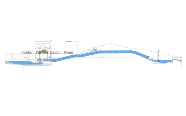
The following is a description of the renewal of the pump system in operation in the Netherlands. The plant has been in operation for 40 years, consisting of two parallel pumps. It runs for 1500 to 2000 hours a year and drains the polder areas behind the dike.
The existing pump drive should be converted from diesel engine with gearbox to an electric motor with a frequency converter. Due to increased requirements, the volumetric flow rate Q should rise from 280 to 340 m3 / min (+21%), and the head H should rise from 4.5 to 6.0 m (+33%). For cost reasons, the highly efficient existing impeller should continue to be used. Further requirements are a cavitation-free operation and a maximum drive power of 400 kW.
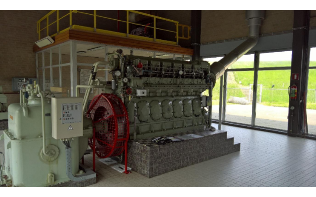
Fig. 2 Diesel drive of the old pump
First, the overall hydraulic state of the existing plant was analyzed by a 3D flow simulation and it was compared with experimental data. This has become the basis for potential improvement. With a relatively small investment, some substantial improvements should be achieved.
Parametric redesign of the pump
For the existing pump designed in 1967, there were only paper drawings are available. The pump model was reverse engineered in CFturbo. The redesign could be completed in less than 2 hours. As a result, a parametric 3D geometry model was available. Once you have a rebuilt parametric model, the pump can be easily modified in any important detail. The path to 3D flow simulation is straightforward because CFturbo includes a comprehensive export interface to the CFD code SimericsMP that was used here.
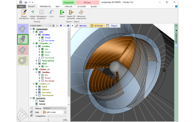
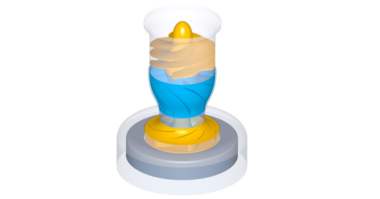
Fig. 3 Redesigned impeller and casing (CFturbo)
Computational analysis of the current state
As mentioned before the transfer of the geometry from CFturbo to SimericsMP is straightforward thanks to a direct interface. Before carrying out a 3D-CFD analysis, the computational mesh has to be generated within SimericsMP (Fig. 4). The mesh is generated automatically. The output is a hexahedral binary tree grid.
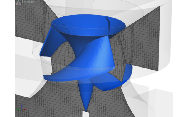
Fig. 4 Calculation grid (control volume) in the middle plane (SimericsMP)
Before calculating the modified geometry, the actual state was simulated in order to compare the calculation results with existing experimental results. This validation shows that SimericsMP correctly reproduces the head, efficiency and shaft power at a given speed and volumetric flow rate. The experimental and simulated data matched very well. The results of the current status were the basis for comparison to all new-designed or modified geometries to evaluate potential for hydraulic improvement.
Hydraulic enhancement of the pump
The task could be solved by applying the deep knowledge of pump hydraulics of an experienced engineer. CFturbo software played an important role in this process using its unique capabilities in parametric pump design. Specifically, the rotational speed was increased from 153 rpm to 174 rpm. At the same time the shaft was renewed and the inlet casing has been completely redesigned. Special emphasis was give a uniform undisturbed inflow velocity profile to the impeller.
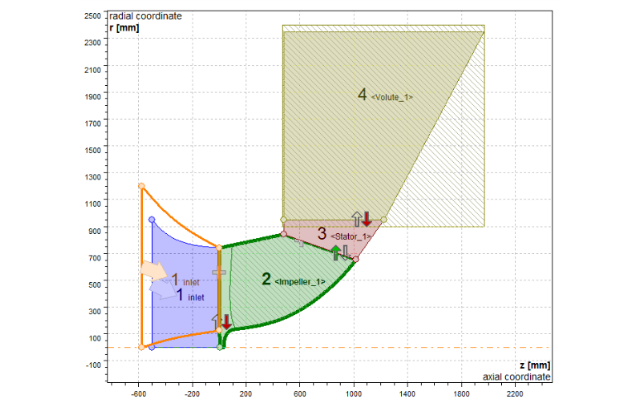
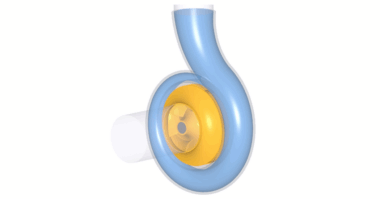
Fig. 5 Pump with new inlet housing (CFturbo)
Achieved results
Due to improved inflow conditions and a more efficient throughflow the pump could reached a significantly increased performance curve. This was achieved by just a moderate increase in rotational speed by 13.72% from 153 rpm to 174 rpm.
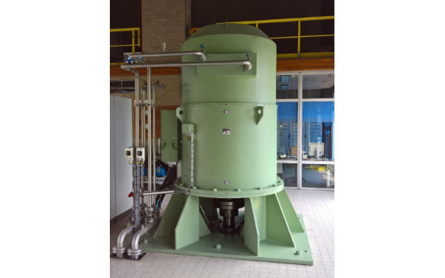
Fig. 6 Electric drive of the new pump
The required driving power of the pump will be between 370 kW and 390 kW. Even under overload conditions it would be below the limit of 400 kW. For the main operating range which is supposed to be between 260 m3/min and 360 m3/min, the NPSHR value will be clearly below the NPSHA level. No cavitation is expected under normal operating conditions.
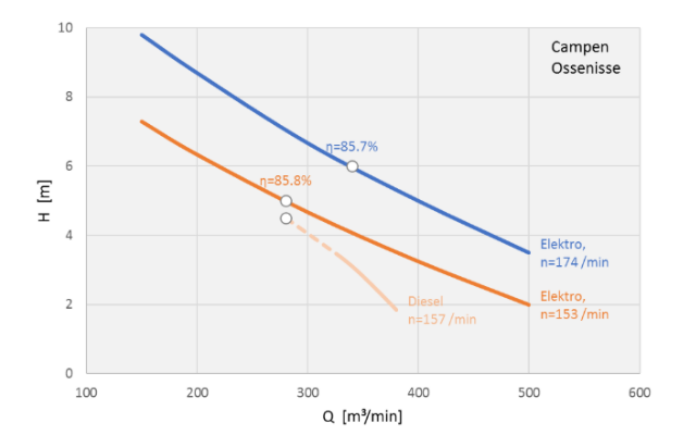
Fig. 7 Measured pump characteristics
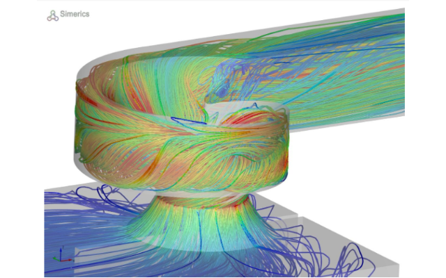
Fig. 8 Flow through the pump (SimericsMP)