
All engineers know Newton’s Laws. A valve closure, pump trip in liquid systems, steam turbine trip in steam systems or any other operational change will propagate pressure waves in the piping system that can generate dynamic loads in pipe legs upwards of 10,000 lbf (50 kN).
Maintaining system safety and function requires a system designed with these transient fluid forces in mind. These forces can be accurately calculated with Newton’s Laws, but simplifying assumptions are often made.
A typical approximation is to consider only pressure forces and assume that fluid friction and momentum effects are negligible. In some cases, forces from this approximation are very close to the true values, which has led to widespread use of pressure-based methods. However, in some typical system configurations, the neglected terms become important, and the pressure-based method dramatically misestimates the true forces.
A complete calculation of Newton’s Laws is impractical without the use of modern computational tools.
Fortunately, tools like AFT Impulse (for liquid transients) and AFT xStream (for steam and gas transients) can handle these complexities with ease – always delivering accurate forces.
Let’s Throw Some Apples
Engineers who design piping need to account for all pipe forces so they can ensure the pipe supports are sufficiently strong, of the right type, and in the right location. ASME B31 code, for example, requires engineers to consider a wide range of factors that relate to pipe structural integrity. Two of those factors are transient pressures and the resulting imbalanced transient forces that result from surge transients in liquid and steam/gas systems.
Surge transients are often called waterhammer in liquid systems and steam hammer in steam systems. The high (acoustic) velocity pressure waves in these applications can cause short duration but high amplitude imbalanced forces – especially in configurations such as pipe runs between elbow pairs. Forces in excess of 10,000 lbf (50 kN) are common.
Fig. 1 depicts a wave propagation at acoustic speed, a, and resulting forces.
a. At the top of Fig. 1 the transient has not started, the pipe run 1-2 is in equilibrium, and no imbalanced force exists.
b. In the center, the wave is initiated at the right from a valve (not shown) which is closed instantly. The wave travels at acoustic velocity, a. When it reaches the pipe run 1-2, an imbalanced force exists that pushes the pipe elbow assembly to the right. This force must be supported by external pipe supports or the pipe elbow assembly will bend and literally move to the right.
c. At the bottom the wave has passed the pipe run 1-2 and the entire elbow assembly. While now at a much higher pressure than at the top, pipe run 1-2 is again in equilibrium and no imbalanced force exists any longer. Note that if the wave reflects from a boundary point on the left, it will travel back through the elbow assembly and exert another imbalanced force.
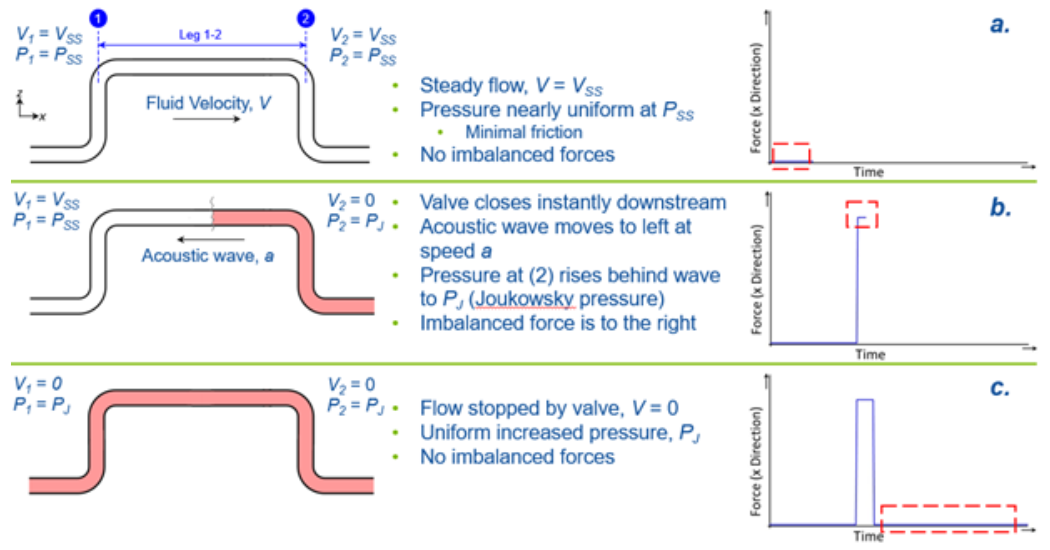
Figure 1. Transient imbalanced force on an elbow pair 1-2 due to an instant value closure.
Take Another Look: It’s more complex than most engineers realize
At first glance this would not seem to be an overly complicated task. But the underlying reality is much more complex than most engineers realize.
Newton’s Second Law of Motion can be employed to assess the maximum forces. However, one first needs a reasonably accurate transient fluid dynamic solution available in order to plug in the pressures and velocities into Newton.
Due to the resulting complexity, engineers have often used a simplified approach they believe to be conservative. Frequently this involves using the Joukowsky Equation or something similar to determine a maximum pressure differential. This pressure differential is then used to estimate a force as shown below. This simplified approach can be called the Endpoint Pressure Method.
Endpoint Pressure Method (simplified approach, from Fig 1b)
 (1)
(1)
Since we know the values of P1 and P2 in Fig 1b, we can write Eq. 1:
 (2)
(2)
While perhaps appropriate for an earlier generation of engineers who designed piping using slide rules, calculators, or even spreadsheets, this simplified approach is fraught with potential error and often badly misestimates the forces. It can even be unconservative and give design loads much too low. And in the incorrect direction!
Waterhammer software such as AFT Impulse™ can be used by engineers to determine transient pressures and velocities for liquid systems. However, engineers often take the resulting software output and attempt to use Newton by only considering pressure forces (e.g., they still use Eq. 1). This approach might seem to be appropriate, but in fact it mistakenly disregards certain parameters in Newton such as forces due to friction and momentum changes in the liquid. While it is true these disregarded parameters are often minimal and can be safely neglected, there are many cases where they are important and cannot be neglected. AFT Impulse performs a complete force balance using all parameters in Newton and is thus able to give a more accurate force prediction. More on this below.
Gas and steam transients often do not generate sufficiently high transient forces to merit detailed simulation. However, there are some applications which do. One such application is steam hammer in large diameter power station piping. Simulating such behavior is significantly more complicated than for liquids. AFT xStream™ is designed to handle such challenging applications and, from what we can tell, it is the only commercially available software that can do this for transient steam flow. Moreover, and similar to AFT Impulse, AFT xStream is designed to account for all parameters in Newton’s Second Law.
So, what is wrong with Eq. 1?
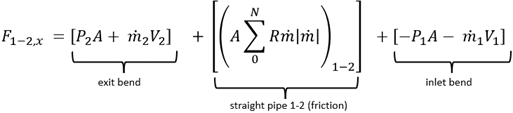
The complete force balance can be determined as follows:
Component Reaction Method (complete method)
 (3)
(3)
where the pipe force from frictional resistance is given by summing the friction in each computing section, 0 to N, as follows:
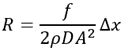
Eq. 3 is called the Component Reaction Method. Comparing Eq. 3 to Eq. 1, it is clear that Eq. 1 is a special case of Eq. 3. First, the fluid momentum, , can and does change from point 1 to 2 because of the waterhammer wave. Second, there is friction in the pipe. If each of these terms is negligible, then Eq. 1 is a reasonable approximation to the force. Often these terms are negligible. However, there are cases when they are not. The ASME papers explain this.
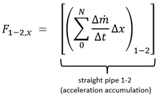
Further, Eq. 3 is not that difficult to use for liquid surge transients. But for steam transients (or gases in general) it is more complicated to determine the needed parameters. Fortunately, if one draws a different control volume around pipe run 1-2 in Fig. 1, it can be shown that an equivalent way of calculating the force is given by:
Acceleration Reaction Method (complete method)
 (4)
(4)
Eq. 4 sums up the change in acceleration for each computing section, 0 to N. It is therefore called the Acceleration Reaction Method. It is valid for liquids and gases. It can be shown that it is complete and yields the same force predictions as Eq. 3. And when a computational solution is available through a simulation model, it is straightforward to use.
To go more in-depth and learn how to apply Eqs. 3 and 4 to these situations, you can check out:
Accurately Predict Transient Fluid Forces in Piping Systems, Part 1: Fundamentals
Accurately Predict Transient Fluid Forces in Piping Systems, Part 2: Applications
Eqs. 1, 3 and 4 are cross-plotted vs. AFT Impulse results in Fig. 2. Here you can see that the simplified approach in the Eq. 1 Endpoint Pressure Method obtains inaccurate and unconservative force predictions.
What is the Right Way to Bite the Apple?
AFT recommends the use of the Eq. 4 Acceleration Reaction Method for general use by all engineers. It includes all terms in Newton’s Second Law and will not lead engineers astray. The Eq. 3 Component Reaction Method is also complete and safe to use but can be more difficult to calculate in practice.
Thanks to the advancement of technology, it’s not a stretch to complete these calculations efficiently. Using AFT Impulse and AFT xStream are great options to make this an easy task.
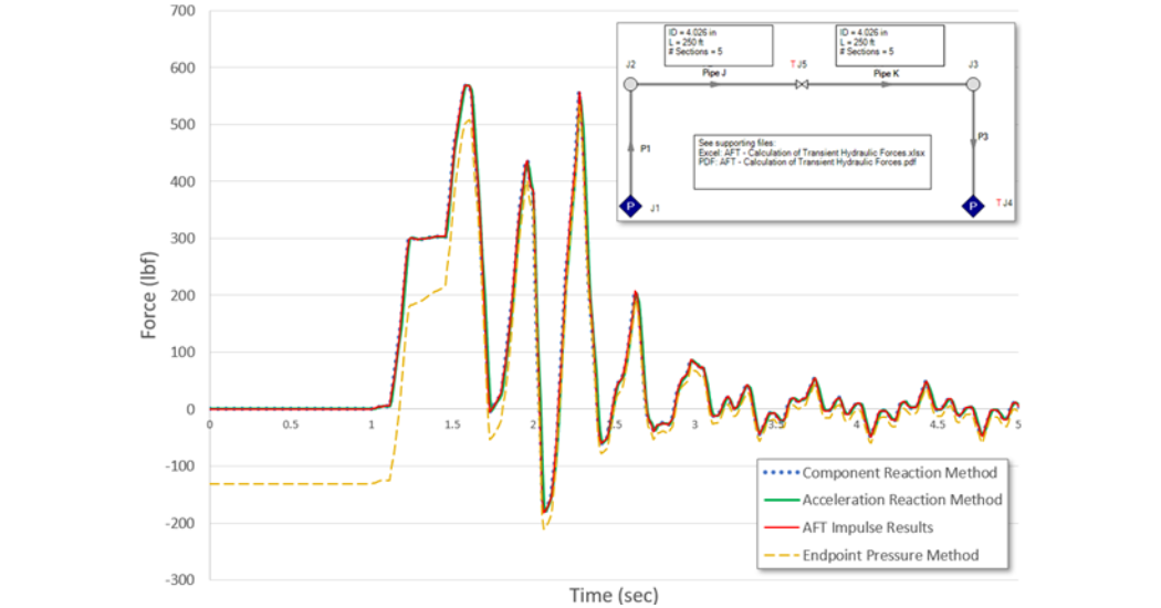
Figure 2. Force predictions for the system shown at upper right using Eqs. 1, 3 and 4. AFT Impulse results are cross plotted. The Impulse results lay on top of the Component Reaction Method and Acceleration Reaction Method.
To learn more about applying Newton’s Laws to predicting forces in piping systems, and to see how AFT’s transient simulation tools make calculating complete and accurate transient forces practically effortless, you can check out this webinar on Predicting Transient Pipe Forces Caused by Water and Steam Hammer.
*Originally published with ASME