By: Joachim Becker ABB Stotz-Kontakt GmbH, Heidelberg, Germany, joachim.becker@de.abb.com
In any modern society, the continuous availability of electrical power is vital. Without power, most residences, commercial businesses and industrial plants would be paralyzed. This electrical power must be delivered to the end user safely and reliably and it is here that distribution switchgear plays a major role. Due to the obvious hazards involved, such switchgear, or the local distribution board, must be designed to protect the installation from faults by switching off the faulty circuit and, simultaneously, guaranteeing the continued operation of nonaffected circuits.
Breaker types
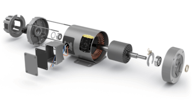
A short circuit places equipment under great stress. Therefore, when designing the switchgear assembly or distribution board, the thermal and dynamic stresses caused by the maximum short-circuit current at the connection point on-site must be considered. To prevent damage to the installation (or personnel) short-circuit protection devices are used to switch off the short-circuit current at the connection point →1.
Most often used for this switching task are molded-case circuit breakers (MCCBs) →2, miniature circuit breakers (MCBs), residual current operated circuit breakers (RCCBs) and residual current operated circuit breakers with overcurrent protection (RCBOs). These devices are marked with their maximum short-circuit capacity to allow the panel builder to select the correct product for the application. Such breakers are suitable for isolation, but switch-disconnectors are usually also installed so that the equipment can be completely de-energized for service or maintenance.
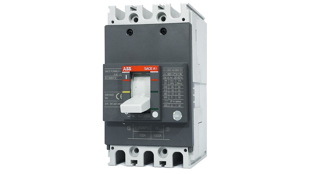
02 ABB A1 frame low-voltage molded-case circuit breaker (conforms to IEC/EN 60947-2).
The uninterrupted short-circuit current
Low-voltage installations are typically supplied by transformers. In such a low-voltage network, the uninterrupted short-circuit current (Ik) is calculated from the rated voltage and the AC resistance (impedance) of the short circuit. A superimposed DC component, which slowly decays to zero, also exists →3. The peak value of Ik is an important value for the short-circuit definitions in the standards.
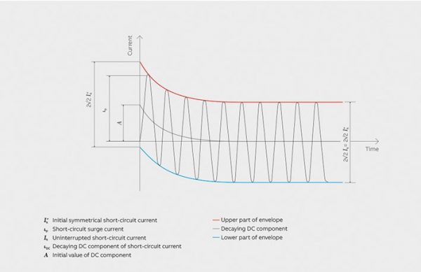
03 Short-circuit current characteristics.
Standards relating to circuit breakers
Depending on the particular application, different standards may be referred to when a designer is specifying circuit breakers or associated equipment for power network protection:
• The IEC/EN 60898-1 standard applies to circuit breakers for overcurrent protection in households and similar installations – for example, shops, offices, schools and small commercial buildings. These breakers are designed to be operated by uninstructed people and without the need for maintenance.
• The IEC/EN 60947-2 standard applies to circuit breakers used mainly in industrial applications where only instructed people have access.
• Switch-disconnectors are tested against the IEC/EN 60947-3 standard.
• Switchgear assembly or distribution boards are tested against the IEC/EN 61439 standard.
Due to the different scope of the standards, in some cases, different definitions are used for the same electrical process. The engineer must, therefore, ensure that he fully understands which particular definition, for, say, short-circuit capacity, applies to the design he is working on.
Circuit breakers and IEC/EN 60898-1
IEC/EN 60898-1 defines the rated short-circuit capacity (Icn) as the breaking capacity according to a specified test sequence. This test sequence does not include the ability of the circuit breaker to carry 85 percent of its nontripping current for a specified conventional time. The service short-circuit breaking capacity (Ics) is the breaking capacity according to a specified test sequence that does include the capability of the circuit breaker to carry 85 percent of its nontripping current for a specified time.
IEC/EN 60898-1 defines fixed values of the ratio of Ics to Icn. The Ics and Icn values are expressed as the root-mean-square values of the prospective short-circuit currents.
To comply with the requirements of the standard for both these short-circuit capacities, the open/close operations of each of three circuit breakers have to be tested. For the open operation, the short-circuit current is initiated at a specified phase angle with respect to the voltage waveform. The three circuit breakers are tested at different angles. The test sequence for Icn is “O – t – CO” where “O” is an open operation and “CO” is a close-open operation, which means that the circuit breaker under test is switched on and experiences the short-circuit current for a certain duration. The time “t” between the operations is 3 min. For Ics, the test sequence is “O – t – O – t – CO” for single-pole and two-pole circuit breakers, and “O – t – CO – t – CO” for three-pole and four-pole circuit breakers. The way the initiation of the short-circuit current is specified in the standard means at least one circuit breaker under test has to switch off at the most severe voltage phase angle.
Circuit breakers and IEC/EN 60947-2
IEC/EN 60947-2 defines the ultimate short-circuit breaking capacity (Icu), also known as the breaking capacity, according to a specified test sequence. This test sequence includes the verification of the overload release of the circuit breaker. In IEC/EN 60947-2, Ics is the breaking capacity according to a specified test sequence that includes the verification of the breaker’s operational capability at the rated current, a temperature rise test and verification of overload release. IEC/EN 60947-2 defines values between 25 and 100 percent for the ratio of Ics to Icn. Again, the Ics and Icn values are expressed as the root-mean-square values of the prospective short-circuit currents. To comply with the requirements of the standard, for both short-circuit capacities each of two circuit breakers have to be tested. In a similar manner to IEC/EN 60898-1, the short-circuit current is initiated at a specified phase angle with respect to the voltage waveform for the open operation, but here the two circuit breakers are tested at the same angle. The test sequence for Icuis “O – t – CO” and “O – t – CO – t – CO” for Ics. The time “t” between the operations is again 3 min and, for opening, the short-circuit current is initiated at a specific voltage phase angle – defined as the angle at which peak current is reached. This peak current is simultaneously the rated short-circuit making capacity (Icm) and is expressed as the rated ultimate short-circuit breaking capacity, multiplied by a factor defined by IEC 60947-2.
Switch-disconnectors and IEC/EN 60947-3
When switches, disconnectors, switch-disconnectors or fuse-combination units are included in a design, the IEC/EN 60947-3 standard is used. A switch-disconnector is capable of switching on and off a current under specified conditions. In the open position, the switch-disconnector provides an isolation function.
As the switch-disconnector is not equipped with an overcurrent release, it must be protected by an MCB, MCCB or fuse. The short-circuit capacity of the combination of switch and circuit breaker is defined as the rated conditional short-circuit current. It is expressed as the value of the prospective short-circuit current the switch-disconnector, protected by a short-circuit protective device (SCPD), can withstand. It is important to keep in mind that the switch-disconnector must be able to withstand the current limited by the SCPD.
This approach is also valid for RCCBs – ie, the short-circuit current stated on the device is the rated conditional short-circuit current of the combination of the RCCB with an SCPD.
A further short-circuit value defined in both IEC/EN 60947-3 and IEC/EN 60947-2 is the rated short-time withstand current (Icw). This value may apply to switches (eg, a switch-disconnector), circuit breakers such as an MCCB or air circuit breaker (ACB), and busbars. Icw is the value of the current the equipment can withstand for a specified time without damage occurring. IEC/EN 60947-2 defines preferred values of this time of 0.05, 0.1, 0.25, 0.5 and 1 s; IEC/EN 60947-3 defines 1 s. For AC, Icw is the root-mean-square value of the current.
The Icw value is important for switchgear with equipment connected in series where the selectivity between the protective devices is realized by a time delay. For example, if a feeder circuit is equipped with an ACB and the downstream branch circuits are protected by MCCBs then to achieve selectivity a time delay is set for the release of the ACB. The installation between ACB and MCCB must withstand the specified short-circuit current for the duration of the ACB time delay.
Low-voltage switchgear and IEC/EN 61439-1
IEC/EN 61439-1 applies to low-voltage switchgear and controlgear assemblies. For assemblies with an SCPD in the incoming unit, the manufacturer must indicate the maximum prospective short-circuit current at the input terminal of the assembly. To protect the assembly, the Icu or Icn of the SCPD must be equal to or higher than the prospective short-circuit current. If a circuit breaker with a time delay is used as an SCPD, or no SCPD is incorporated in the assembly, the Icw with the maximum time delay must be stated.
Application example: copper and copper alloy factory
Suppose a copper factory is supplied from the 20 kV medium-voltage power grid by a 20 kV/400 V stepdown transformer. The rated output of the transformer, Sr, is 1,600 kVA and the rated impedance voltage, ukr, is 6 percent. For distribution transformers with ratings up to 3,150 kVA, the network impedance can usually be disregarded. The short-circuit impedance of the transformer limits the short-circuit current, which is expressed as:

→4 shows the circuit diagram of the power supply.
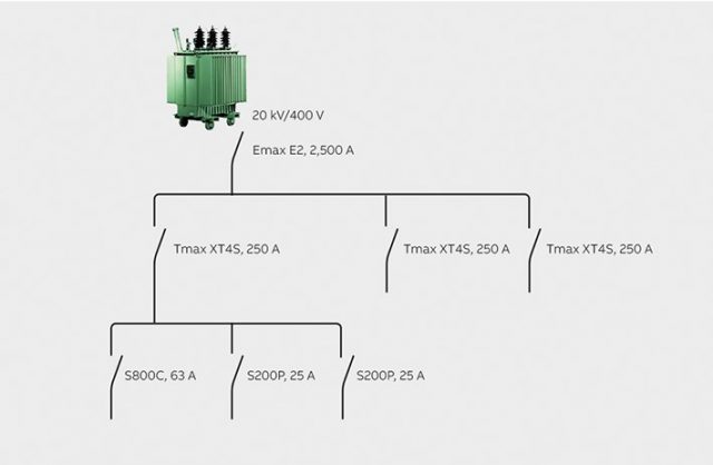
04 Example protection device configuration for an application such as a copper factory.
For the incoming supply, an ABB Emax E2 breaker with a current rating of 2,500 A is used. The distribution level is protected by an ABB 250 A Tmax XT4S breaker. The final circuits are equipped with ABB S800C and S200P MCBs.
To achieve the correct cascading, the following calculation is made: The Icw of the Emax E2 (version B) is 42 kA. The time delay is set to 0.1 s. Consequently, the Emax can withstand the short-circuit current. On the distribution level, the Icu of the Tmax XT4S is 50 kA. The cable between the Tmax and the busbar for the sub-distribution has a cross-section of 95 mm2 and a length of 15 m. The resistance of the cable can be found in technical handbooks to be 0.246 ohm/km.
The resistance of the transformer is 0.00597 ohm. The short-circuit current at the sub-distribution is then:

By using S800C and S200P MCBs, no backup protection is needed as the ultimate short-circuit capacity of these devices is 25 kA. Total selectivity between the Tmax XT4S and S800C, S200P is given.
Application example: power distribution in a large office building
If an office building is supplied from the 20 kV medium-voltage power grid by a 20 kV/400 V transformer, with an Sr of 630 kVA and a ukr of 4 percent, the short-circuit impedance of the transformer once again limits the short-circuit current, which is:

→5 shows the circuit diagram of the power supply.
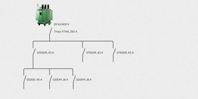
05 Example protection scheme for a large office building.
The Icu of the Tmax XT4 (version N) breaker is 36 kA. The Icu of the ABB S750DR selective main circuit breaker is 25 kA. Consequently, the Tmax and the S750DR are able to break the short-circuit current. The cable between the S750DR and the sub-distribution network has a cross-section of 16 mm2 and a length of 10 m. The resistance of the cable can be found from technical handbooks to be 1.32 ohm/km. The resistance of the transformer is 0.01012 ohm.
The short-circuit current at the sub-distribution level can then be calculated as:

By using an S200M MCB, no backup protection is needed as the ultimate short-circuit capacity is 15 kA. Total selectivity between S750DR and S200M is given.
For the SD200 MCB, shown in →5, the rated conditional short-circuit current is important. The value for the combination SD200/S750DR is 10 kA. Consequently, the SD200 is protected by the S750DR as the maximum short-circuit current at this point is 9.9 kA.
The examples above show that the correct configuration of protective devices can allow distribution switchgear to operate in a safe and reliable way under short-circuit conditions. The various IEC/EN standards mentioned assist designers in choosing the correct ratings for the products they employ and thus ensure that electrical power continues to flow to the application no matter what electrical fault conditions arise.