There are a handful of phenomena that can complicate alignment. Few of them can cause more harm that pipe strain. This article is written from the standpoint of how maintenance personnel can identify and correct many pipe strain issues. Let me clarify that I am not an engineer or piping designer. My observations are simply based on a career as a millwright.
Pipe strain is unwanted pressure or movement in piping systems. It is caused by many things, such as:
• Improper design or installation of piping systems or machinery.
• Thermal or pressure changes which could cause unwanted movement in piping systems.
• The lack of, or improper design and placement of pipe supports.
• Process changes, in which changes in the piping system were not factored in.
Pipe strain can be a complex issue, but it causes straightforward problems:
• Misalignment of coupled machinery.
• Machine casing distortion.
• Excessive thrust or radial loading of bearings, seals, gears, and other machine components.
• Excessive vibration of piping systems, and possible transmission of vibration into the building or surrounding machinery.
Here’s an example.
Recently, I was teaching a shaft alignment training class in the Midwest. This company mentioned that they had a small pump they had been trying to align for two weeks, but there was so much vibration in the machine (even when not running) that the laser transmitter/detectors would not be still enough to get accurate measurements.
I looked at their machine, and indeed, the vibration did seem to be above normal.
The first thing I normally think of is vibration from a nearby machine. But only a few other pumps were running, and they were very smoothly. There was no big reciprocating machine on the floor above.
I had no vibration measurement tool, so I began to just feel around by hand to try and discover the source. The suction line on this pump seemed to have a great deal of vibration in it. It was supported by a clamped pipe support, about 6 feet from the suction flange. I loosened the clamp and the hold down bolts, and the support moved about ¼”. We retightened the bolts.
We went back to the laser alignment tool, and the transmitter/detectors were completely still. Measurements were made, and it was determined that the motor was base bound, or too high to be aligned to the pump. We made a minor vertical correction to the inboard end of the pump (10 mils), and aligned the motor back to the pump. Due to operational needs, we could not test for pipe strain, but the ability to easily move the pump and the reduction in perceived vibration gave us a good idea that pipe strain had been minimized.
If pipe strain is excessive, it can cause harm to machinery components. So, let’s look at some methods to identify and correct it.
Proper Installation
Piping should be designed with the induced moments and forces from piping and machinery in the calculations. Machine bases should be grouted, and allowed to cure for a specified period of time, before the machines are installed on them. The time varies based on the grouting material. Expansion and bellows joints are sometimes used to minimize the forces from piping thermal and dynamic changes. A good rule of thumb is that the piping starts at the pump and works its way back. Machinery should be installed in such a manner to prevent base bound or bolt bound situations. Pipe supports should be designed and installed to support the piping, as well as minimize the amount of piping load on the machine.
If these were done perfectly each time, pipe strain would be minimal. So, why is pipe strain so common?
• Machines are set on uncured or undercured bases.
• Piping is terminated at the pump, instead of being installed working back from the pump.
• Flanges are aligned using chain hoists and come-alongs.
• Piping is “field run”, instead of designed.
• Changes are made once the system is installed, such as valve changes, control changes, and piping re-routes.
• Thermal changes in the piping induce stresses which are transmitted to the machines.
ANSI B31.3 states, “Flanged joints shall be aligned to the design plane within 1/16” per foot across any diameter. Flanged bolt holes shall be aligned within 1/8” max offset”.
So, how can we verify that the piping is inducing strain? The most common method is to break the flange.
A common method is to mount a dial indicator across the flange, and measure for movement of the piping across the flange. This should be done in the vertical, horizontal, and axial planes.
A similar process can also easily be done with laser shaft alignment tools.
The laser method will not tell you how much the flanges have moved, but will tell you if that movement is sufficient to cause a change of shaft alignment between the machines.
• Take a normal set of shaft alignment measurements with the piping connected. Then take another set of shaft alignment measurements with the flange broken. Compare the difference.
• Take a set of measurements (without rotating the shafts) with the flange connected, then another with the flange broken.
This should give you an accurate representation of how much influence the bolted flange connection has on the shaft alignment, which may be more important than the amount of movement as measured across the flange. You should have no more than 2 mils change in the alignment condition when the flange is unbolted. If more than 2 mils of movement is present, start looking for obvious signs of pipe strain. The first thing to check should be the pipe supports.
Pipe Supports
Pipe supports are used to both support the weight of the piping and the material being moved. They should also minimize movement of piping due to thermal changes.
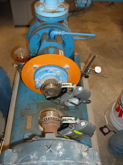
They can be installed to support the piping from underneath, as in this photo. They can bolt directly to the floor, or work in addition to neoprene isolation materials, to minimize transmission of vibration into the structure. Occasionally, they are welded directly to the piping, but usually they work in conjunction with pipe clamps.
Pipe hangers support the piping from above. They often employ the use of threaded rod to connect the pipe hanger to the structure. These are normally not as rigid, and as such, serve to support the weight to the piping and materials, without providing sufficient stiffness to curtail movement due to thermal growth or dynamic forces.
When pipe strain is suspected, check to see if pipe supports are working. Look for:
• Supports – are they in place?
• Hangers with threaded rod. If the threaded rod is moving substantially, or vibrating, see if it is adjusted. It should have some tension on it, since it is supposed to be supporting the piping.
• Stiff leg supports – are they contacting the floor? Are the bolts tight? If the hold-down bolts are tight, loosen them, and see if the support moves. In some instances, loosening the bolts allows the pipe strain to relax, and relieves the strain from the system.
I have had many instances where I used a steel wedge and a hammer to determine loose pipe supports. Often, I suspect it is due to concrete shrinkage. If the pipe support is installed while the concrete is still “green”, the concrete continues to shrink, but the baseplate for the pipe support doesn’t get retightened. Don’t leave the wedge in place – tighten the bolts back down. If the pad is uneven, you may have to shim the baseplate.
The point is, if pipe strain or excessive pipe movement is suspected, snoop around a bit, and see if you can find it. In many instances, just loosening and retightening the hold down bolts on a pipe support can reduce pipe strain.
Some other things to look for:
• Has there been a recent change is the system?
o Is there new piping, new valves, or new machines?
o Has the suction strainer, check valve, or another component been removed and placed back in?
o Can you see evidence that pipe supports have been removed, as in the case of a change in the system?
• Can you see obvious pipe movement, such as swaying?
• Has additional bracing been added?
Thermal Changes in the System
Does the piping system go thru numerous or extreme changes in temperature? This can cause unwanted movement in the piping system.
Many years ago, the company I worked for installed a single stage LP steam turbine to drive an 800 horsepower centrifugal compressor. This required a 90 foot run of schedule 80 piping to feed the compressor from an existing line. Piping was “field run” as opposed to designed. There were 3 hangers, 1 pipe support, and no expansion joints.
We monitored startup vibration levels, which started to increase substantially within 5 minutes of startup. The machine was shut down. We installed several dial indicators to measure movement in the turbine and piping. Almost immediately upon restarting the turbine uncoupled, the indicators began changing. We measured as much as 3/8” horizontal movement in the turbine, all due to thermal changes in the piping system. An engineer was brought in, who redesigned the piping, adding expansion joints and additional supports. The total measured movement after redesign – 2 mils.
In summary:
• If you are going to install piping which goes thru extremes of thermal changes, the system should be engineered to minimize unwanted movement of the piping.
• The piping system should be checked periodically, to insure the piping support system is working.
• Pipe strain should always be considered a factor in precision shaft alignment. If coupled machines have reoccurring shaft alignment problems, pipe strain should be considered a contributing factor.
Discuss more on our industry forum!