In very basic terms, power factor is expressed as the ratio of real power, kilowatts (kW), to apparent power, kilovolt-amperes (kVA). A desirable ratio of near unity results when the real power and apparent power are nearly equivalent. Power factor is an indication of how effectively a load uses power. A high power factor indicates effective utilization of electrical power, while a low power factor indicates poor utilization. Utilities charge higher rates when power factor is low because of the extra burden imposed on the distribution system. Not only does the distribution system have to accommodate the real power being consumed, but it must also accommodate the reactive (non work producing) component flowing within the system.
When sizing motors, engineers are often skeptical to oversize motors due to penalties imposed by utility companies. Penalties in the form of increased charges per kWhr of energy usage are typically incurred by customers operating at poor power factor. Therefore, in order to avoid such penalties, engineers need to be diligent in motor selection. The engineer may choose a motor that provides nearly no excess headroom for the application instead of choosing the next larger size motor in fear of operating the larger motor at low power factor. This often results in the need to test the selected motor to closely scrutinize the selection is not undersized for the application. In extreme cases, reduction in machine productivity may result due to selection of a motor that is only marginal for the load. Here, machines may not support future productivity increases due to the tightly selected motor.
As energy charges increase, consumers are looking for ways to increase power factor to keep energy expenses low. In these cases, variable frequency drives (VFDs) can be used to provide flexibility in motor selection. VFDs can be used to improve system power factor when oversized motors or motors that operate at low power factor are used. Here’s how.
A good way of understanding power factor is to consider the equation:
Power Factor = Cos Θ/(√[1 + THD2])
where: Θ = displacement angle between fundamental voltage and current
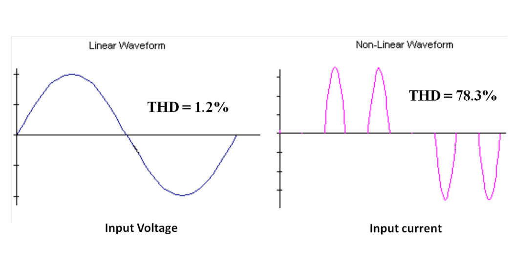
THD = total harmonic current distortion
The above equation takes into account fundamental displacement and harmonics. Both affect true (overall) power factor.
A motor operating directly from a sine wave supply (commonly referred to as “across-the-line” operation) will exhibit displacement between the applied voltage and resulting current. The displacement varies as the motor load changes. Typical values for displacement, Cos Θ, are 0.85 for
heavily loaded motors and 0.65 for moderately loaded motors. Lightly loaded motors may appear as pure inductors in which the power factor is nearly zero.
Total Harmonic Distortion, THD, is typically very small when operating a motor from a sine supply. The nearly pure voltage sine wave applied to the motor results in a nearly pure current sine wave with extremely low distortion. Typical sine wave THD values are on the order of 2-3%. Therefore, displacement power factor, Cos Θ, is the predominant term one needs to consider when dealing with motors that operate directly from utility power. A heavily loaded motor with a power factor near or above 0.85 is therefore desirable over a lightly loaded motor.
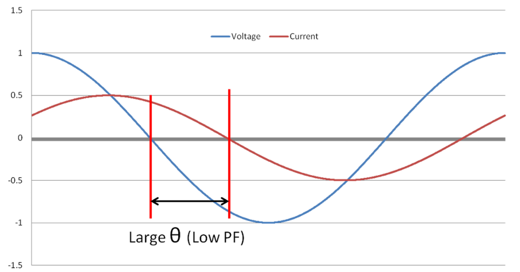
Figure 1: Lightly Loaded Motor
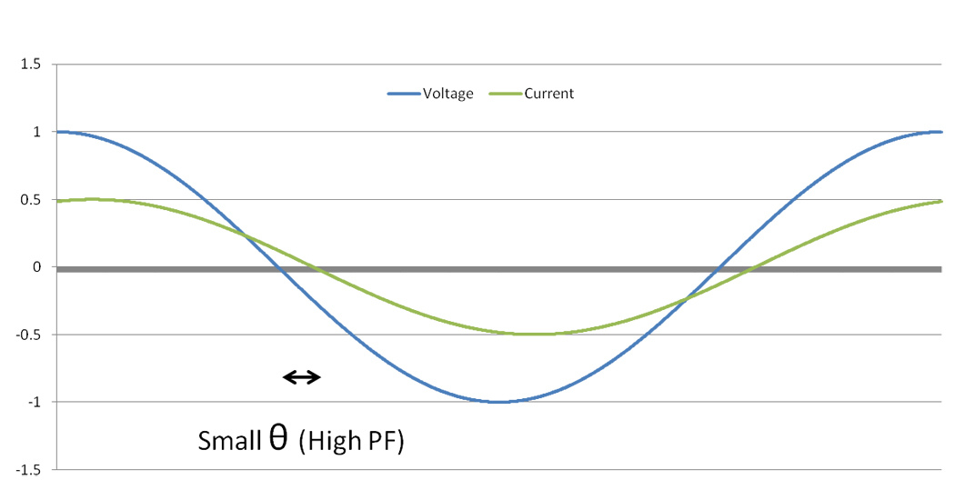
Figure 2: Heavily Loaded Motor
A motor operated by a VFD will exhibit similar displacement of the fundamental voltage and current. However, this displacement is not reflected back to the supply (input side of VFD) due to the rectification that is incorporated with today’s PWM VFD’s. Diode, and sometimes IGBT based, rectification keeps the input fundamental displacement near unity. In other words, drive input current remains in phase with the supply voltage under all load conditions. Therefore, Cos Θ is near unity (approximately 0.98) with VFD use. On the other hand, diode and IGBT rectification may result in relatively substantial current THD. A typical full wave diode bridge rectifier will result in approximately 45% current THD. This is a typical value for a VFD with DC link choke under fully loaded condition. Using 0.98 for displacement (Cos Θ) and 0.45 for THD in the above equation, the resulting PF will be approximately 0.89. If the VFD incorporates an IGBT based PWM rectification scheme the THD may be considerably lower. An IGBT based rectification configuration typically includes substantial input impedance so that the PWM converter switching is not reflected back onto the supply. THD level on the order of 5% can be expected. Here, a power factor of 0.98 can be possible for full load.
 Now, one must also consider the power factor that occurs at lighter loads. Under light loading, drive input displacement power factor remains near unity due to the diode rectification. However, VFD input current THD will increase. It is not uncommon for THD to be near or even above 100% under lightly loaded conditions. Applying a large THD to the above equation results in substantially reduced power factor. However, this in itself is not as bad as it may seem.
THD is a ratio of the harmonic component (Ih: non-fundamental component) to the fundamental current component (I1).
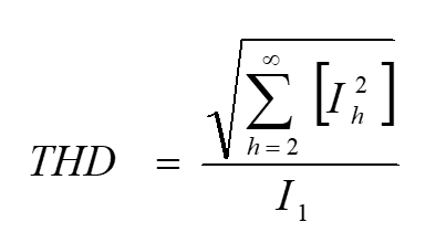
Current THD increases partially because the harmonic component increases, but, also because the fundamental component decreases. THD increases to what appears to be a significant level, but, the actual overall harmonic current component itself is quite small as compared to the full load current. Overall, VFD input current will be nearly zero as the largely reactive current flowing into the lightly loaded motor does not get reflected back to the supply. The reactive current is supplied by the VFD DC link circuit (bus capacitors) and circulates within the VFD’s output section. It does not flow from the supply side. Therefore, even though drive input PF is low with the lightly loaded condition, the VFD inputcurrent is also much lower because only the “real” current (torque producing) component is reflected back to the supply. The resulting harmonic current is quite small even with the high THD level and does not represent any significant issue for the supply and associated components. Therefore, the low PF encountered with a lightly loaded VFD is not a detriment to the system and effective use of power is maintained.
For example, a lightly loaded motor operating across-the-line will continue to draw 25-35% of rated current as magnetizing current (reactive current). This current is at nearly 90 degrees displacement fromthe applied voltage making for a very low power factor system. The supply and associated components will be exposed to this substantial current at low power factor. This same current will flow to the motor when operating from a VFD, however, the VFD input current will be near zero because this reactive motor current is supplied solely by the VFD DC link circuit. Only the real (torque producing) component is measured on the supply side. Even though drive input PF is lower due to increased harmonics at light load, the input current is also much lower. Subsequently, the low input power factor does not negatively impact the overall supply components (transformer, wiring, etc.) that are already sized to accommodate full load operation in the first place. Over sizing of supply components that is typical for low power factor systems is not required because the VFD input current is also low.
Expanding on this, motors with low power factor will exhibit a large magnetizing current (reactive current). An additional benefit of using a VFD is elimination of the magnetizing component from being reflected back on the supply. VFD input current can be less than the motor current even at 60Hz operation. This will hold true for motors with relatively low full load power factor (less than approximately 0.85) and VFDs that maintain high overall input power factor (0.89 or greater).
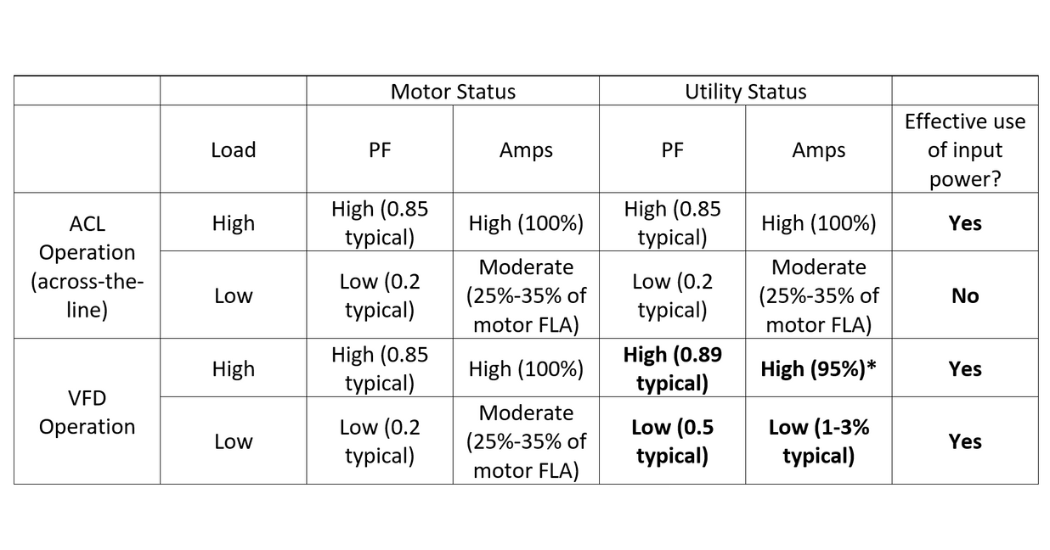 * VFD input current is lower than the motor current because motor magnetizing current is not reflected back onto the supply and input power factor is high.
Table 1. Power factor and current summary for VFD and across-the-line motor operation.
In conclusion, consider using a PWM based VFD that offers a DC link choke or some other form of power factor improvement such as an input line reactor when power factor improvement is desired. Effective utilization of energy can be maintained even when motors are oversized to accommodate future production increases. Lower overall input current to the VFD/motor system and improved overall “system” power factor can be realized. This will result in lower utility charges.
Read more about VFDs.