For some unbeknownst reason, engineers and technicians in the motor control industry associate a PLC as being a necessary component for VFD control. This may have rung true years ago, but VFD technology has progressed and made technological leaps and bounds just as much as other technologies in recent years. VFDs have reached the maturity level that eliminates the need to install and program a PLC which was previously needed to make many applications function. This advancement results in overall cost and space savings. Additionally, wiring and programming complexity is reduced significantly.
A very common example where a VFD can step up to the plate and take over the functionality of a PLC, is a pumping application. Many pumping applications run a PID loop to determine required motor speed. Simply put, a PID loop will consist of a set-point, feedback, and tuning for the PID loop. Frequently, a PLC is utilized to process the entire PID loop and simply output an analog speed reference to the VFD.
In this case, the VFD is being underestimated since most entry-level VFD’s have their own PID loop which can be enabled and setup with only a small handful of parameters. The set-point is entered directly into the VFD’s programming. This eliminates the need to juggle between the VFD’s keypad and a PLC’s often pricey computer software. Feedback from a transducer is landed directly to the VFD’s analog input.
With these two commanding values input, the drive can now determine if the motor should speed up or slow down to meet the set-point. This maximizes energy efficiency, since the motor is only running fast enough to meet the demand of current set-point value. Cost is lessened as a PLC does not need to be purchased or programmed. Also, space is dramatically reduced since the entire process runs off of the VFD.
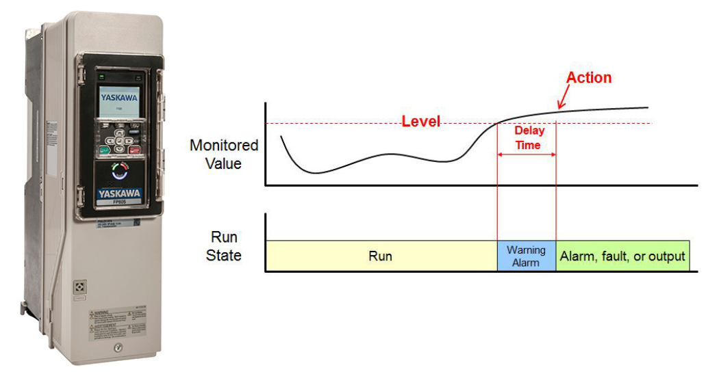
A PID process loop is a relatively simple example which only scrapes the surface of the potential processing power of a VFD. Sticking with pumping applications, VFD’s can protect the pump motor and the application with a minimal amount of programming needed. On a specialty pump VFD, protection can be setup in three basic steps; level, delay, and action.
The level is a value at which point a protective feature is triggered. This level can be based on current, frequency, voltage, feedback, etc.
The delay will determine the amount of time the value being monitored can stay above or below that point before action is taken.
After the delay time expires an action is taken. This action includes, faulting out the VFD, alarming, or closing a digital output contact on the drive.
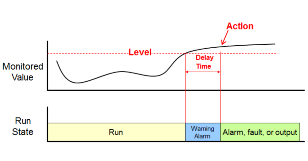
Figure 1. Most VFD protective and application specific programming can be broken down into three parts; a level, delay, and action
The VFD has the ability to monitor current, frequency, feedback, voltage and many other critical values. The ability to monitor these values also gives the VFD the ability to protect countless VFD and pump related components, which can avoid potentially hazardous running conditions.
Consider a condition where prime is lost on a pump’s suction side. The simplest and most effective way to determine that prime has been lost is to monitor the current drawn by the pump motor. To protect the pump from a loss of prime occurrence, a motor current detection level in the VFD must be set just above the motor’s no load current. The reasoning behind this is that if prime is lost, the current drawn by the motor will be reduced. If the output current drops to the no load current, which is right below the set detection value, the VFD will perform the desired action after the programmed delay time. This protects the pump from overheating due to the dry run without the need for additional components.
Those three basic programming steps (level, delay, and action) for loss of prime are copied and pasted through-out the majority of a VFD’s programming. Another example would be some form of high pressure relief or detection which is a necessity on any pump application. With a pumping VFD, a high feedback level can be programmed into the VFD. Following suit, a delay time and an action for this new condition must be set. Once properly set-up, if the system’s pressure were to reach the high feedback level the VFD can halt pump operation before damage occurs. The VFD can also be programmed for a low feedback detection situation that functions in the same fashion.
In addition to providing protective features such as loss of prime and high and low feedback levels, VFD’s offer a wealth of programmable functions that can provide a variety benefits for different applications. Irrigation systems commonly consist of long and intricate lines of plumbing. When an irrigation system is operating it is important to first pre-charge the system. Pre-charging simply means running the VFD at a relatively low fixed speed to slowly fill or pressurize the system. Pre-charging is beneficial as it will eliminate any hammering of valves which occur with an otherwise fast pump speed.
Setting up the pre-charge function only requires three parameters to be programmed, just like the aforementioned features. For pre-charge, a fixed frequency must be determined. This frequency is called the pre-charge frequency and is the frequency at which the VFD will run while in pre-charge mode. Pre-charge mode will activate when a VFD receives a run command. Pre-charge will run at the programmed pre-charge frequency until one of two criteria is met.
This necessitates the requirements of two additional parameters; the pre-charge level and pre-charge time. The sole function of these two parameters is to end pre-charge. The pre-charge level uses the transducers feedback to determine at what level to end pre-charge. This is usually in pounds per square inch (psi). Alternatively, the pre-charge time is the maximum time the VFD can run in pre-charge mode, regardless if the feedback level is ever reached.
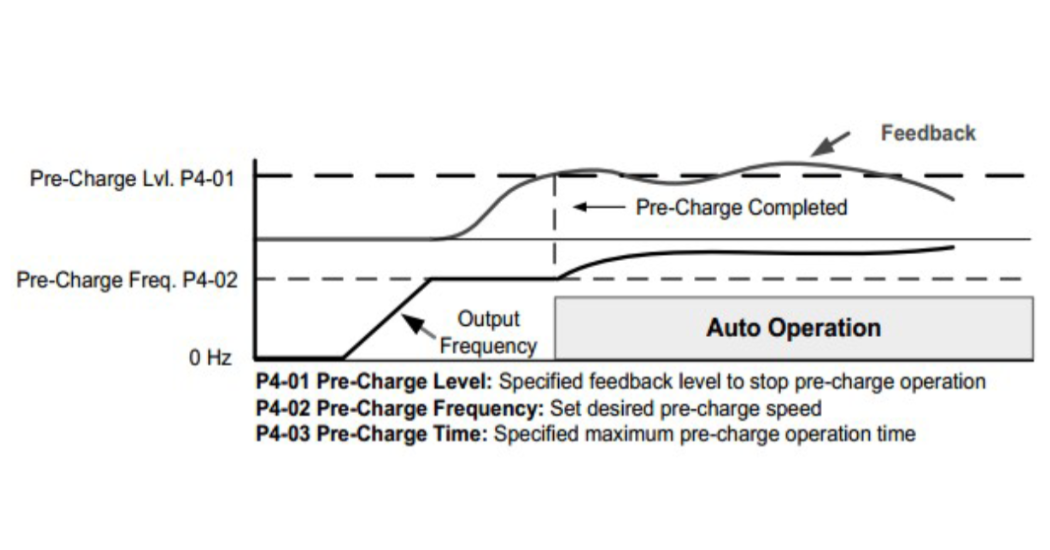
Figure 2. The VFD ends pre-charge once the maximum pre-charge time expires or the pre-charge level is met.
These examples are just a sample of a VFD’s true potential as far as protective functions and application specific features. Though all of these features and parameters may seem overwhelming, keep in mind the consistency with parameter set-up. Also weigh in the potential space savings and resultant money savings by eliminating unnecessary PLC’s and additional hardware.