Contributor: Charles Kolstad
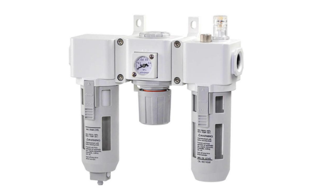
In a pneumatic system, air leaving the compressor is typically unsuitable for any intended application. The compressed air is usually wet, dirty and at the incorrect pressure, which are characteristics that could damage downstream equipment. An FRL (Filter, Regulator, Lubricator) is used to condition compressed air to the right quality and can be seen in Figure 1. An FRL unit is a system that is comprised of three separate units that carry out different phases of conditioning: filtration, regulation and lubrication. Although often used as a single system, it doesn’t always come as a single unit. Rather a single regulator unit or filter-regulator unit is used. Lubricators are typically not used in modern pneumatic systems with self-lubricating equipment.
Filter
The filter (Figure 2) gets rids of any contaminants such as dust, water, vapour or oil present in air leaving the compressor. Proper filtration is crucial in maximizing the longevity of downstream equipment. Since filtration is the first stage of conditioning, the filter is usually installed upstream of other equipment. It operates by first creating a cyclonic action of incoming air. This deposits heavy contaminants at the bottom bowl. Next, the compressed air is forced through a filter mesh of adequate size, effectively filtering out contaminants. Over time, the accumulated contaminants and moisture are removed in either of the following ways, depending on the type of the filter: manual or self-draining. Manual filters require the machine to be turned off before the filter can be drained, while self-draining filters have an automatic float-controlled valve that periodically drains the filter. There are three types of filters, categorized by their level of filtration. They are:
- General purpose filters which remove particulate matter and water
- Oil removal filters which also remove oil and vapour
- Removal filters which also remove vapour in addition to dust, oil and water
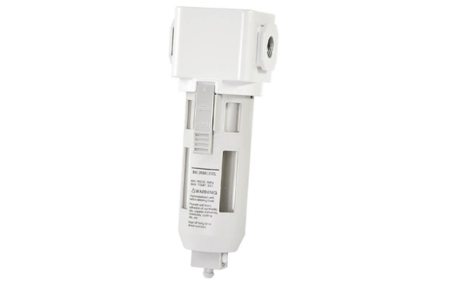
Figure 2: Example of an air filter with semi-automatic drain valve
Pressure regulator
The regulator (Figure 3) controls the pressure of compressed air in a pneumatic system. It regulates the pressure of the air that is supplied to downstream equipment. This unit is particularly necessary for fluid power applications such as blow guns, pneumatic cylinders and air logic valves. Regulators are also called pressure reducing valves. The desired pressure for an application is set using a control knob mounted on the regulator. This knob adjusts the internal diaphragm and needle valve assembly to ensure the correct output pressure. Regulators are generally one of two types; relieving or non-relieving. Relieving regulators have the ability to be adjusted from high to low pressures. When necessary, these regulators will exhaust excess downstream pressure. Non-relieving regulators on the other hand cannot relieve downstream pressure. Therefore, other methods of releasing trapped air have to be employed. Regulators are available either as a single unit or as a filter-regulator two in one unit.
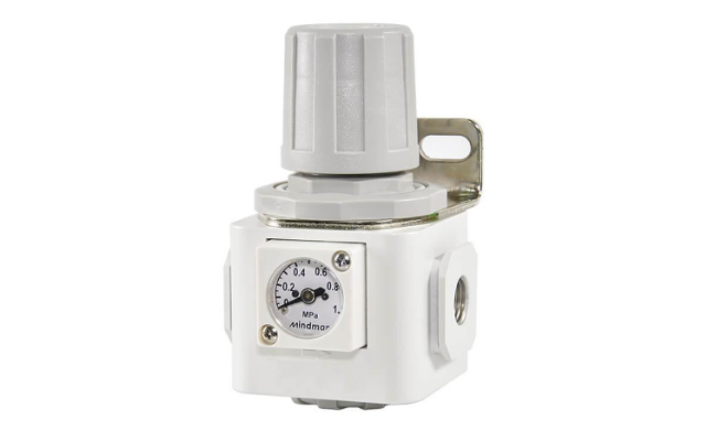
Figure 3: Pressure regulators reduce the pressure to a constant, adjustable level, even if the input pressure is not constant
Lubricator
A lubricator (Figure 4) introduces controlled amounts of oil into the flow of compressed air. There are two types of lubricators: oil-fog and micro-fog. In oil-fog lubricators, oil is directly deposited as relatively large droplets into the air flow. On the other hand, micro-fog lubricators first atomise oil droplets to sizes of about 2µm before introducing them into the air flow. Lubrication is necessary to reduce the friction generated in moving components. Air driven equipment such as valves and air motors need lubrication to increase their life span. However most pneumatic systems are self-lubricating and so lubricator units are not always required.
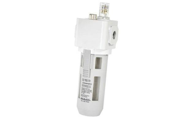
Figure 4: Lubricators add a controllable amount of oil to the air flow
Selection criteria
Size of filter element
The level of filtration achievable is dependent on the size of the filter element. The higher the level of filtration required, the smaller the filter element size. A 40µm filter would filter out all particles larger than 40µm in size. It is important to note that filter size also affects pressure. The finer the filter, the higher the pressure drop. Therefore, the acceptable pressure drop for an application should be considered when selecting a filter size. The expected pressure drop for a given filter is usually specified by the manufacturer. For applications where both high pressure and maximum filtration are crucial, compensation can be made by using a higher power compressor. The sizes of filter elements and their corresponding levels of filtration are categorised as follows:
- General purpose filters: These filters come in sizes of either 40µm or 5µm. Filters of size 40µm effectively remove particulate matter and about 90% of water. A 5µm sized filter removes all particulate matter and water present in compressed air.
- Oil removal (coalescing) filters: These 0.3µm sized filters effectively remove oil, as well as water and particulate matter. This kind of filter is necessary for applications where oil is a damaging contaminant, such as spray painting and for breathing apparatus.
- Vapour removal filter: This ultra-fine filter is sized at 0.01µm. It is capable of filtering out not only particles, oil and water, but also vapour.
- Activated carbon filters: These filters are employed in applications that require very high levels of purity such as food and pharmaceuticals. They are capable of removing odor and taste, along with every other impurity.
Pressure rating
The required pressure of compressed air varies for different applications. Once the suitable minimum operating pressure has been determined for a particular compressed air application, it is crucial for air to be supplied at a constant pressure, regardless of upstream fluctuations. Regulators are rated in a standard 0.05 – 1Mpa regulated pressure range. They are generally available in operational pressures of 0.1, 0.2, 0.4, 1.0 and 1.6Mpa. The proof pressure is the maximum pressure above which the regulator cannot operate, or it may be damaged. It is essential to know all pressure ratings of a regulator before selecting it for an application.
Port size
The port size determines the flow rate in an FRL unit. The required flow rate for a process or system is essential in selecting an FRL of a port size. The higher the required flow rate, the bigger the port size of the selected unit should be. The port size for the required flow rate can be determined using the flow factor formula for gases.
Lubricator type
There are two types of lubricators and their selection is dependent on their intended usage:
- Oil-fog lubricators are best suited to heavy applications such as heavy load cylinders and single tools. They are ideal for level runs and short distances.
- Micro-fog lubricators on the other hand are ideal for complex, multi-component systems. They are best suited for non-level runs and long distances.