The release of AFT xStream 3 brings with it reciprocating compressors for your gas transient models! Positive displacement compressors now have two subtypes: fixed flow rate for a steady mass or volumetric flow rate, as was present previously, and the all-new reciprocating compressor option. The reciprocating compressor model is for compressors in which one or more reciprocating pistons drive gas flow.
This capability allows for better modeling of systems with such compressors, as they are inherently more transient in nature than their centrifugal counterparts with steadier flow. Previously, this periodic nature could be approximated using periodic flow transients with simple sinusoids or chopped sinusoids.
However, that method is not appropriate for all cylinder configurations and forces the flow rate to match user assumptions instead of calculating flow from compressor geometry and the state of the system. Because that approach used assigned flow junctions, it also could not capture system interactions with the suction and discharge side of the compressor simultaneously – doing this with two separate assigned flow junctions for suction and discharge could conserve mass, but pressures and temperatures at those junctions would be unrelated to the other junction, and energy would not be conserved.
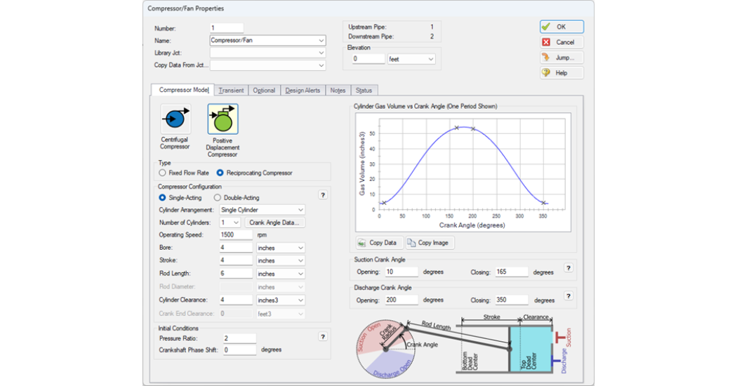
The reciprocating compressor model removes these limitations, allowing the discharge and suction conditions to interact holistically with each other and with the broader system. These system interactions also have the benefit of making the reciprocating compressor model more appropriate than periodic flow transients for systems with other transient events, like valve transients, or inherently transient junctions, such as finite tanks. The reciprocating compressor incorporates the effects of compressor geometry, such as bore, stroke, clearance, rod geometry, and valve timing, as shown below.
Single stage reciprocating compressors with multiple cylinders can be modeled with a single compressor junction. This can accommodate up to six cylinders in single cylinder, inline, opposed, and vee cylinder arrangements. Modeling multiple cylinders in this way, crank angle offsets between each cylinder are handled automatically, and the compressor properties window provides a graphical representation of each cylinder’s gas volume with valve timing events, crank angle offsets, and the crankshaft phase shift for the compressor overall (if applicable). In addition to single-acting configurations with a single compression chamber per piston, double-acting compressors with compression chambers on the crank and head ends of the piston can be modeled, and the impact of the piston rod on chamber volume is accounted for. For all configurations, the cylinder geometry and arrangement are used with gas thermodynamics to determine transient pressure and flow in and out of the compressor.
If you only have an approximation for your compressor’s pressure ratio, don’t let that stop you from setting up your transient model! Even when a pressure ratio is supplied by a compressor manufacturer, this value will differ from the pressure ratio observed in the system because this is influenced by the flows and pressures throughout the system. While the pressure ratio input affects steady state results and therefore initialization of your transient model, the compressor will stabilize to a transient solution driven by compressor geometry alone, as shown below.
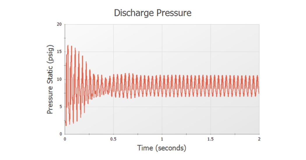
Figure 2: Transient results with approximate pressure ratio stabilize to geometry-driven pressures
While compressors with multiple cylinders can be modeled with a single compressor junction, this may not always be the ideal approach. It is possible to model each cylinder as an individual compressor, and this approach still allows for frequency analysis using the AFT xStream Pulse Frequency Analysis module! Simply set the pulsation Source in the Pulse Setup panel to a user defined reciprocating compressor and specify the correct speed and number of heads.
The most common situations where this approach is preferable are when you are modeling a multistage compressor, modeling a compressor with a cylinder arrangement or crankshaft offsets unavailable in the preset options, or wanting to capture the impact of manifold effects. All these situations are applicable to the model shown below.
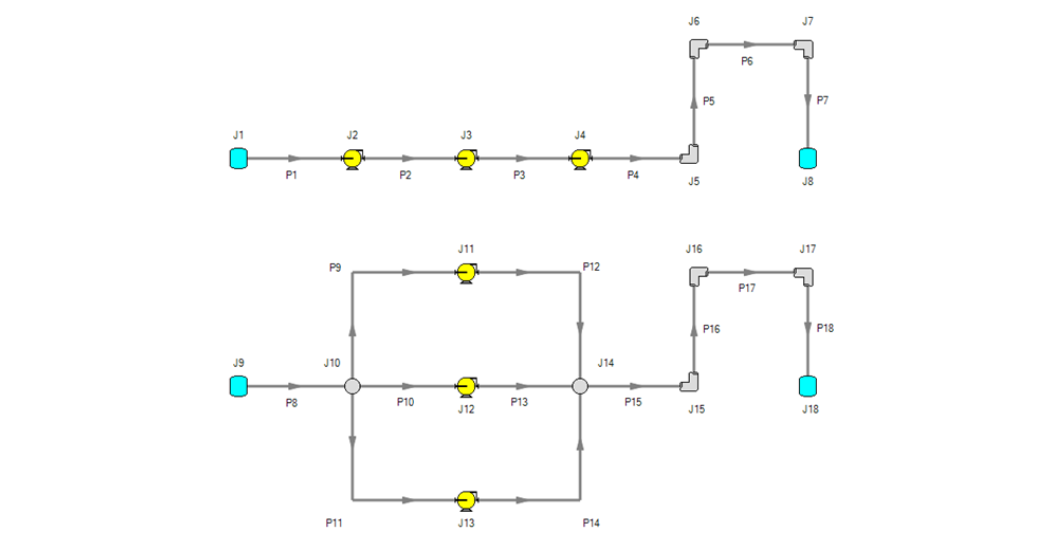
Figure 3: Submodels represent a three-cylinder multistage compressor (top) and a single-stage three-cylinder compressor with manifolds (bottom)
It is common for multistage compressors to have smaller bores for each successive stage to maintain roughly the same power requirement for each cylinder as pressure increases from stage to stage. This is easily accommodated with separate junctions and will be used for the design of the series compressor in this example. The main parameter to keep in mind when modeling cylinders separately is the crankshaft phase shift, which changes the reference angle for each crank arm. For the parallel and series design approaches above to be equivalent, the crank events would need to be evenly spaced for the parallel design, and the operating speed of the series configuration would be three times that of the parallel unit. The cylinders in series are assumed to have a 180-degree offset so the discharge stroke of one cylinder coincides with the suction stroke of the next. The resulting compressor configurations for each cylinder are shown in the table below.
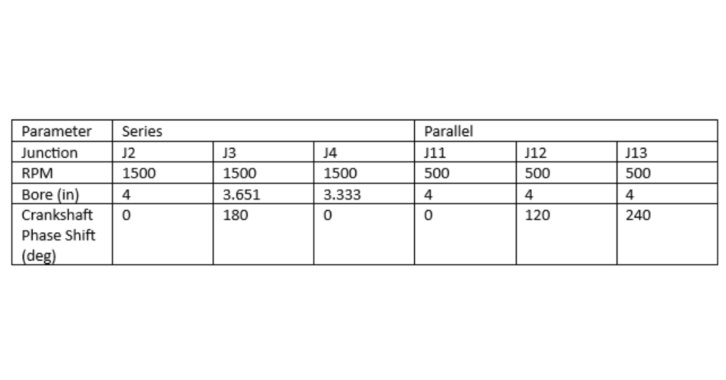
Table 1: Example compressor inputs for parallel and series three-cylinder compressors
Reciprocating compressors are powerful modeling tools that expand the systems that can be modeled and analyses that can be performed in AFT xStream. The built-in presets make them easy to use while still allowing enough flexibility to accommodate other approaches.