Summary
The rapidly expanding use of diesel engines and a-c variable speed drive systems has made it essential for test stand users and designers to acquire a working knowledge of torsional effects. Both drive types carry a much higher risk of associated component failures than either spark ignition engines or other variable speed motor types. The diesel’s high amplitude torsional output is well known. The problems associated with a-c drives stem from the very wide range of output torque forcing frequency. Unless such drivelines are analyzed and modified where necessary, there is a high probability resonance will fall within the operating speed range and cause component failure. Technical Memorandum 8150 shows how to estimate torsional resonant frequencies and describes how to avoid destructive effects. Both practical and theoretical aspects are included. Several typical problems are analyzed and solutions presented.
Background Discussion
All mechanical power producing devices – hydraulic motors, air motors, electric motors, internal combustion engines – have discrete poles. As a result, their output torque is not developed smoothly but has periodic torque pulsations or torsional vibrations. These torque variations in turn, produce periodic velocity variations or accelerations. Thus, in addition to having an average torque and speed value, the input (forcing function) to a shaft network has a fundamental frequency and multiples or harmonics of that frequency. This dynamic forcing function is applied to power transmitting and consuming devices which invariably include complex mechanical networks. When the fundamental forcing frequency, or one of its harmonics, is equal to the torsional resonant frequency of the network, a significant torque magnification can occur. That is, the applied peak-to-peak torque variations can be increased by a significant factor.
Avoiding Problems
The preferred method of avoiding the destructive effects of torsional resonance is to place a flywheel (with a large moment of inertia) between the source of torque pulsations and the remainder of the network and/or to use torsionally soft elements (couplings, shafts, etc.) in the driveline. Both tactics lower the system resonant frequency (Fr). That reduction allows operation well above resonance and thus attenuates rather than amplifies the torsional effects. Stated in other words, the modified shaft network is a low pass filter that prevents the torsionals from propagating to the rest of the system.
If other considerations prohibit the use of a flywheel, it is often possible to operate well below resonance. Under these conditions, the resonant frequency should be at least 2.5 times the highest forcing frequency. When operating well below resonance, the fundamental torsional pulsations will be seen by the shaft network without either significant magnification or reduction. Therefore, all component stresses must be low enough to survive the peak torques and be fatigue rated for the peak-to-peak torque reversals. Damping will reduce the magnification factor at resonance and can be added by using fluid couplings. However, they introduce power loss which is not acceptable in most applications.
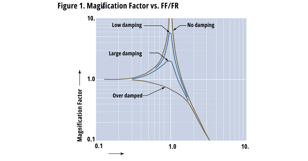
Since all driveline components must handle the peak torque – the sum of the average driveline torque and the peak torque variation – one or more of those components can fail even though it is conservatively rated to handle the average torque. A fatigue failure is most likely to occur when high frequency torsional vibrations are present. However, if the resultant peak torque is high enough, even a yield failure is possible. Figure 1 illustrates the torque multiplication effect of torsional resonance. When the forcing function frequency (Ff) is equal to the torsional resonant frequency (Fr), the multiplication is a maximum. It can approach infinity with no damping present. In severe service, such as diesel drivelines, it is not unusual to find resonant torque (and therefore stress) magnifications of two to seven times. From Figure 1, one can see the torsional variations are reduced in amplitude, rather than increased, when the torsional resonant frequency is well below the forcing frequency.
 Useful Formulae
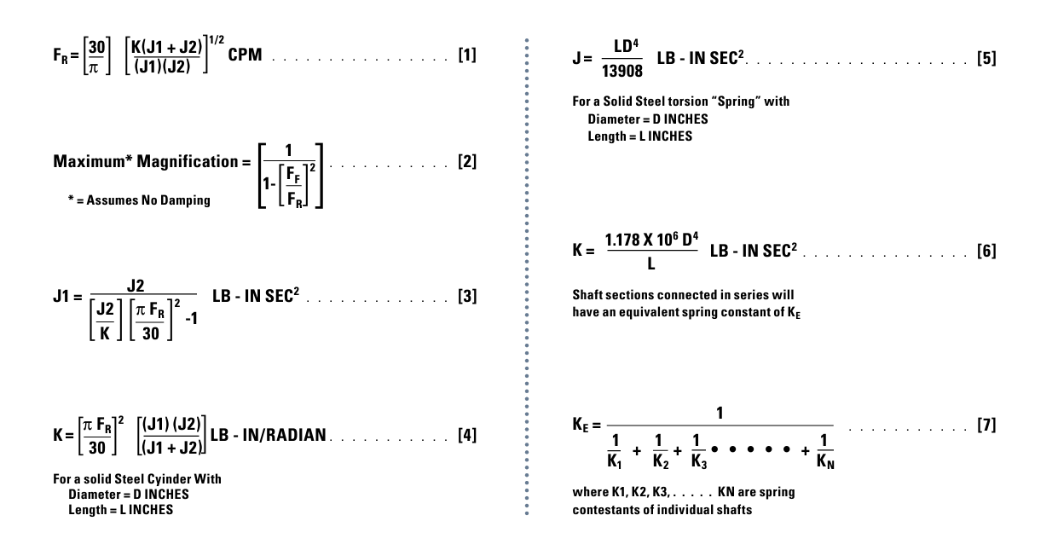
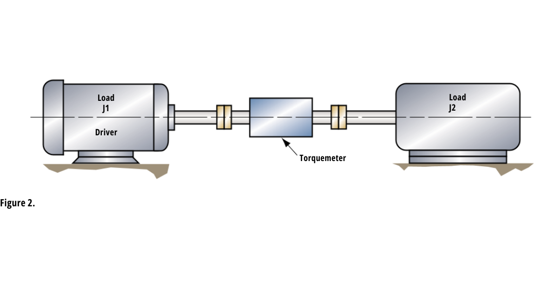
In diesel drivelines, it is especially important that the torsional resonant frequency be well below the operating speed range. A mechanical schematic of a diesel engine dynamometer is shown in Figure 2. In such a dynamometer the test engine drives the absorber through a torquemeter and flexible couplings. It may be classified as a two mass, single spring system and is typical of motor-generator sets and similar machinery installations. The inertia of the load (J2) and the test engine flywheel and crankshaft (J1) are usually large compared to the inertia of the torquemeter and the shaft couplings. Thus, the system resonant frequency may be computed by using Equation 1 where,
J1 is the moment of inertia of the engine in LB-IN SEC²
J2 is the moment of inertia of the absorber in LB-IN SEC²
K is the torsional stiffness of the torquemeter in LB-IN/RADIAN
 Practical Examples General
Torsional resonance is of great practical importance in the examples analyzed. The first two cover diesel engines which produce high amplitude torque variations. A motor with variable frequency drive system is discussed in Case 3. Analysis of variable frequency drives is necessary because their speed ranges are typically 5 to 15 times greater than diesel engines and, because the probability that destructive resonance will occur increases with the speed range.
Case 1, A Safe Diesel Installation A 2,000 HP at 1,050 RPM, 12 cylinder, 4 cycle diesel engine is to be tested on an engine dynamometer over the speed range from 400 to 1,200 RPM. An MCRT 28008T (2-5) 200,000 LB-IN torquemeter measures torque and speed. The absorber is a generator/load combination. The following data summarizes the installation characteristics:
J1 (engine crankshaft and flywheel) = 2,400 LB-IN SEC2
J2 (absorber inertia) = 4,530 LB-IN SEC2
K = 29,000,000 LB-IN/RADIAN (see Bulletin 761)
Ff, minimum = 400 RPM X 12*/2 = 2,400 CPM
Ff, maximum = 1,200 RPM X 12*/2 = 7,200 CPM
*Forcing frequency out of a 4 cycle IC engine is one half the product of the shaft speed and the number of cylinders.
Equations 1 and 2 can be used to calculate the shaft network resonant frequency and maximum possible (no damping) magnification factors. The results are summarized below:
Fr = 1,298 CPM (equal forcing frequency occurs at 216RPM)
Maximum Possible Magnification at 400 RPM = 0.41
Maximum Possible Magnification at 1,200 RPM = 0.03
There is virtually no risk of damage from torsional resonance because the resonant frequency of the network is significantly lower (54%) than the lowest operating speed. Calculated maximum magnification factors confirm this situation.
Case 2, A High Risk Diesel Installation
A 135 HP at 1800 RPM, 6 cylinder, 2 cycle diesel engine will be tested on an engine dynamometer. An MCRT 28061T (6-3) 6000 LB-IN torquemeter is used to measure torque and speed. Power will be absorbed by an eddy current brake over the speed range from 700 to 2500 RPM. The following data summarizes installation characteristics:
J1 = 0.75 LB-IN SEC2
J2 = 6.6 LB-IN SEC2
K = 2,430,000 LB-IN/RADIAN (see Bulletin 761)
Ff, minimum = 700 RPM X 6* = 4,200 CPM
Ff, maximum = 2,500 RPM X 6* = 15,000 CPM
*Forcing frequency out of a 2 cycle IC engine is the product of shaft speed and the number of cylinders.
Using Equations 1 and 2 to calculate the shaft network resonant frequency and magnification yields the following results:
Fr = 18,139 CPM (the equal forcing frequency occurs at 3023 RPM)
Maximum Possible Magnification at 700 RPM = 1.06
Maximum Possible Magnification at 2,500 RPM = 3.16
Because the maximum operating speed is close to resonance, the installation as described will have a high risk of failure. To avoid this, the system resonant frequency must be reduced, preferably to half (or less) of the lowest forcing frequency. Alternately, the resonant frequency could be increased to 2.5 (or more) times the highest forcing frequency.
In this case, it is impractical to significantly increase the system resonant frequency, i.e., the inherent inertias cannot be reduced and the torquemeter has an extremely high stiffness for its size. The only practical approach is to reduce the resonant frequency by decreasing the shaft stiffness and/or increasing system inertias.
Since the MCRT 28061T (6-3) torquemeter is extremely stiff, substituting an MCRT 28004T (6-3) torquemeter will significantly lower the resonant frequency. Its stiffness is 515,000 LB-IN/RADIAN (see Bulletin 761). From equation 1, its use will reduce the resonant frequency to 8351 CPM (or 1392 RPM). That resonance is within the operating speed range and could result in destructive torque multiplications. Therefore, in addition to reducing the shaft stiffness, it is necessary to increase the system inertia.
Using Equation 3 to calculate the driver inertia required to reduce the resonant frequency to 1800 CPM (300 RPM), yields a negative inertia. That means it is not possible to achieve the desired resonance by simply adding inertia to the driver side. The best way out of this dilemma is to add a torsionally “soft” dynamometer coupling shaft and, if needed, to add inertia on the driver side. A reasonable selection is the Spicer 15-50 dynamometer shaft which has a stiffness of 98,220 LB-IN /RADIAN and maximum ratings of 7,680 LB-IN and 4500 RPM. The equivalent network stiffness for this shaft and the MCRT 28004T (6-3) torquemeter may be calculated from Equation 7. It is 82,488 LB-IN/RADIAN.
The installation modified with this “soft” shaft and using the MCRT 28004T torquemeter has a resonant frequency (from Equation 1) of 3,342 CPM. At the lowest speed the magnification factor is 1.73. Thus, the resonant frequency is still too high to be absolutely safe. It is necessary to add inertia to obtain a safe, 1,800 CPM (300 RPM) resonant frequency. Equation 3 is again used to calculate the driver inertia needed. That value is 3.58 LB-IN SEC 2 . The required minimum additional inertia becomes 3.58 less 0.75 or 2.83 LB-IN SEC 2 .
Assuming a 12” diameter steel disc, Equation 5 indicates that 1.9” of length will produce the desired inertia. Of course, the resulting assembly should be dynamically balanced and fitted with safety covers. By way of summary, this critical application required both a significant reduction of network stiffness and increased inertia to obtain safe operating conditions – torsional resonance equal to less than half the lowest forcing frequency. The modified system characteristics are summarized below:
J1 = 3.58 LB-IN SEC2
J2 = 6.6 LB-IN SEC2 K = 82,488 LB-IN/RADIAN
Fr = 1,800 CPM (the equal forcing frequency occurs @ 300 RPM)
Ff, minimum = 4,200 CPM
Ff, maximum = 15,000 CPM
Maximum Possible Magnification @ 4200 CPM (700 RPM) = 0.23
Maximum Possible Magnification @ 15,000 CPM (2,500 RPM) = 0.01
Case 3, A Variable Frequency Motor Driveline
A 15 HP, 4 pole, a-c motor with variable frequency speed control package is to be tested on a dynamometer over the speed range from 90 to 1,800 RPM (corresponds to 3 Hz to 60 Hz excitation). The drive has current limiting, which in turn, limits the maximum starting torque to 175% of rated or, 920 LB-IN. An MCRT 28002T (1-3) 1,000 LB-IN torquemeter measures torque and speed (see Note). The absorber is an eddy current brake. The following data summarizes the installation characteristics:
J1 = 0.48 LB-IN SEC2
J2 = 0.71 LB-IN SEC2
K = 70,100 LB-IN/RADIAN (see Bulletin 761)
Ff, minimum = 3 CPS X 60 SEC/MIN X 2* = 360 CPM
Ff, maximum = 60- CPS X 60 SEC/MIN X 2* = 7,200 CPM
*Forcing frequency out of an a-c motor is twice the input power frequency.
Using Equations 1 and 2 to calculate the shaft network resonant frequency and maximum possible magnification factors yields the following results:
Fr = 4,724 CPM (equal forcing frequency occurs at 39.37 Hz input or 1181 RPM)
Maximum Possible Magnification @ 3 Hz input = 1.01
Maximum Possible Magnification @ 60 Hz input = 0.76
Because the resonant frequency falls in the operating range, the installation has a high risk of failure. The preferred solution is to reduce the resonant frequency to one half or less the lowest forcing frequency. In this case, to 180 CPM or less. One approach is to reduce shaft stiffness. Substituting the above values in Equation 4, indicates the shaft stiffness must be reduced to 101.75 LBIN/ RADIAN, assuming the inertias remain unmodified. Inserting a torsion spring with that stiffness will produce the desired change.
A one inch diameter torsion rod will handle the required torques. Substituting that diameter and the required stiffness in Equation 6 yields a required spring length of 11,578”. Clearly, this is an impractical approach. Similarly, if one calculates the inertia required to reduce the system resonance to 180 CPM, the inertias are totally impractical (about 395 LB-IN SEC2 for both driver and load) for the physical size of the motor, absorber and torquemeter.
The only alternative is to raise the resonant frequency above the operating range – to at least 2.5 times the highest forcing function or, to 18,000 CPM. Again, using Equation 4 reveals the system spring constant must be equal to or greater than 1,017,548 LB-IN/RADIAN. This can be accomplished by substituting a very stiff torquemeter, such as the MCRT 28060T (2-3), for the MCRT 28002T. The modified system characteristics are summarized as follows:
J1 = 0.48 LB-IN SEC2 J2 = 0.71 LB-IN SEC2
K = 1,375,000 LB-IN/RADIAN (see Bulletin 761)
Ff, minimum = 360 CPM
Ff, maximum = 7,200 CPM Fr = 20,924 CPM
Fr/Ft Max = 2.91
Maximum Possible Magnification @ 360 CPM = 1.00
Maximum Possible Magnification @ 7,200 CPM = 1.13
Maximum Possible Magnification @ 14,400 CPM*=1.90
*Second harmonic of 7,200 CPM
By way of summary, the most practical solution to this problem was to raise resonance well above the highest forcing frequency – 2.9 times. The relatively high magnification factor at 14,400 CPM is acceptable because the magnitude of forcing function harmonic input is substantially less than the magnitude of the fundamental.
NOTE: When started across the line without current limiting, a-c motors can develop several times their rated torque. In the Figure 2 dynamometer system, the motor starting torque accelerates two major system inertias; J1 and J2. Under these conditions the torque seen by the torquemeter is:
(Starting torque developed by motor) X (J2/(J1 + J2))
For across the line starting without current limiting, the torquemeter full scale rating should be equal to or higher than this value. If it is not, a failure may result.
This information provided by S. Himmelstein and Company. For more information contact info@himmelstein.com, or visit: www.himmelstein.com