When applying variable speed control to deepwell submersible pumps, there are some unique concerns that need to be taken into consideration due to the mechanical design of the pump. One of these concerns is how to protect the pump bearings.
Most deepwell submersible pumps use fluid film thrust bearings instead of ball and roller bearings used in most surface mounted pumps. The unique thing about this type of bearing is that there are no moving parts within the bearing, so if the motor is controlled correctly there are fewer risks of parts failure.
The thrust bearings are water lubricated and require a certain flow in the bearing to push the two metal parts apart and create the water film between them. In order to create the required pressure with minimum risk of galling the pump needs to reach the minimum speed as fast as possible. The specific speed required depends on the pump design and should be requested from the pump manufacturer.
When applying variable speed drives, this is usually done through adjustment of the ramp to secure that minimum speed is reached within the time frame given by the pump manufacturer. This adjustment is very simple and can be made in any drive on the market today.
Now that the protection of the bearings is taken care of, it is time to look at the control loop. With the fast ramp applied the pump reacts very quickly to changes in the feedback signal. As a result the risk of water hammer increases significantly and the need for measures to protect against this needs to be evaluated.
If the pump is simply filling a tank and there are no sharp angles, filters or check valves in the pipeline to tank, this might be acceptable. The pressure surges will simply result in a burst flow into the tank. If on the other hand such equipment is there, then the risk of significantly reduced life time or even instant damage will increase significantly.
In most installations the ramp time of the pump becomes a compromise between the protection against galling in the thrust bearing and water hammer deterioration of the system. Watch this video to learn about the effects and causes behind water hammer.
A problem, which is however often ignored, is that once the system is up and running and water hammer creates noise in the system, especially in the valves, the operator will start optimising the ramp to remove this, as he knows that this type of noise is damaging the valve itself, jeopardizing the protection of the bearings. Most operators forget why the ramp is set so fast in the first place, simply because the impact of a longer ramp time is not apparent, when making the adjustment. Those who are aware will likely think; “I am sure a small adjustment can’t hurt with all the safety margins that are applied”.
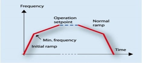
What is really needed is to be able to set the fastest possible ramp on the drive until the minimum speed has been reached and then change to an operational ramp, which is optimised for system protection. This can however only be done if there is either a means of changing the ramp times dynamically or if the drive has a function, which sets dedicated ramps for starting and stopping the motor. Such dedicated ramps are typically found as “initial ramp” and “final ramp” in the drives programming menu. Below shows how the ramp profile would look for a drive, which has this feature.
 The initial ramp secures that pressure is built up in the thrust bearing during the start by setting a fast ramp just below the trip point of the drive. Normal ramp operation will then be used only for optimisation to control loop performance. This will prevent most of the water hammer issues, as the pump does not built much pressure in the pipeline below its minimum speed.
The final ramp secures that the pump is stopped slowly, until reaching the minimum speed, where the pumps addition to system pressure is close to zero. It then stops the pump very fast to protect the bearings against galling and the pump itself against cavitation damages. If the normal ramp is maintained during stop, there will be galling every time the pump is stopped. Galling will reduce the life time of the pump and will not be covered by any warranty of the pump manufacturer. Also while the pump is stopping there will not be any flow in the pump from the time it passes minimum speed. Depending on the pressure in the system, this could result in cavitation damages.
If a soft starter is used instead of a VFD, it is important to select a soft starter, which can provide the same type of initial torque response during start up, but also incorporates an advanced acceleration control to protect against water hammering. An example of such a soft starter is the Danfoss MCD500, which includes both Kickstart and adaptive acceleration control (AAC).