Author: Heinz P. Bloch, P.E.
Mechanical seals are components that keep the pumped fluid (or “pumpage”) confined to the pump casing. These seals are installed at the location where the shaft enters or leaves the casing and their purpose is to prevent leakage. There are many hundreds of styles and sizes and configurations of seals. All use the underlying principles of stationary and rotating face combinations (Fig. 1). Some are simple and inexpensive; others are complex and deserve special attention (Ref. 1).
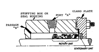
Fig. 1: Operating principle and essential nomenclature of mechanical seals
Conventional mechanical seals often apply spring pressure or some other closing force to the face of the rotary unit in Figure 1. However, many mechanical seals are designed with a single coil spring, others with several small coil springs, still others with pleated bellows applying a closing force to the stationary seal part. They are called rotating mechanical seals if, as configured in Figure 1, the spring-loaded face is part of the rotary unit and is clamped to the shaft. It wobbles, so to speak.
We use the term stationary seal whenever a spring-loaded closing force is applied to the non-rotating (stationary) seal unit. Stationary seals are advantageous when there is known shaft deflection and in shaft systems that operate at high peripheral velocity. As the shaft deflects under load, a conventional seal will have its springs moving at all times. Not so with stationary seals. As the shaft deflects, the spring or springs in a stationary seal will compress or elongate only to accommodate the new shaft inclination/deflection. In other words, the face will always be at a right angle (90 degrees) to the shaft.
In all cases and regardless of seal type, designs that place the springs away from the process fluid are generally preferred over designs that allow process fluid to contact the springs. Also, all seal assemblies need some kind of vent provision, be it a port “A” or a simple vent passage “B” (Figure 1). In some instances, not providing an appropriate vent passage will doom the seal.
Still using packing?
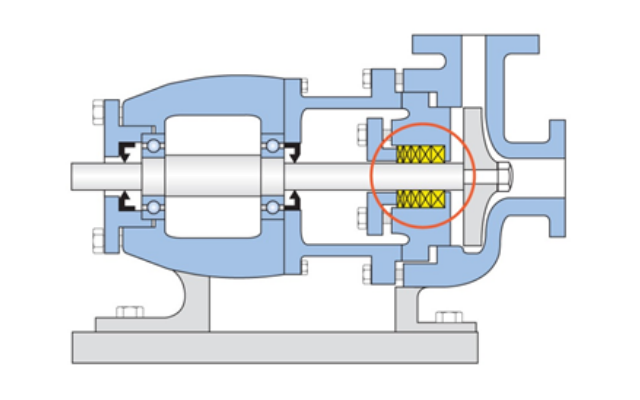
Since about 1950, mechanical seals have almost totally replaced the more maintenance-intensive compression packing previously used in process pumps (Figure 2 above). But suppose you are presently in the process of converting to mechanical seals. In that case and until conversion work is completed, use this installation and servicing sequence:
–Distinguish between different packing styles and materials; be sure to use the right one for the application
–Preferably use a mandrel to properly wrap-and-cut new packing
–Use the right tool to remove old packing
–Remove corrosion products from shaft or sleeve surface
–Coat ring surfaces with an approved lubricant
–Insert one new ring at a time; then seat each ring using a proper tool
–Install packing gland, initially only finger-tight
–Operate for run-in, initially allowing an uninterrupted stream of sealing water leakage
–Tighten sequentially to allow flow of 40-60 drops per minute Be aware that inadequate leakage flow generates much heat, burns up packing and damages the shaft surface.
General overview of mechanical seals
Working with a competent seal manufacturer avoids mistakes and adds value (Ref. 2). Reliability-focused users never view mechanical seals as a cheap standard commodity. These users select only experienced seal manufacturers and cultivate relationships based on mutual trust. Long-term customer service and consistent application of thorough engineering products and best available work procedures benefit all parties and are of much greater importance than short-term returns obtained from initially paying a low price. A single failure incident often causes price-related gains to vanish in a flash—both literally and figuratively. Optimized seal flush piping arrangements are needed to create the most appropriate seal environment.
There are generally two main groups:
1) “Flush” — Clean, cool liquid is injected into the seal chamber to improve the operating environment. A second, smaller port is provided and normally oriented downward. It often serves as a leakage observation or vent opening.
2) “Barrier or Buffer” used with dual seals — A secondary fluid is fed to the space between two sets of mechanical seals to prevent ambient air from contacting the pumped fluid, to improve seal cooling, and/or to enhance safety.
It is worth mentioning that not all mechanical seals require special external flush arrangements. Still, for long and trouble-free life the mating faces shown in Figure 1 must somehow be separated and/or cooled. Cooling prevents the liquid film between mating seal faces from vaporizing. Not all seals require cooling and quite often the pumpage itself can serve as a suitable separating and cooling fluid between the seal faces.
However, the very small gap (typically 0.0001 to 0.0003 inches) between faces can be taken up by either liquid or gas. Different face configurations and API (American Petroleum Institute) flush plans (flush schematics) accomplish that; these plans vary because they must accommodate different fluid parameters, conditions, and properties. All flush plans are described in vendor literature and industry specifications such as API-682 and ISO 21049. A few of them are shown in Figures 3 through 8; the ones we have selected here use API plan numbers and are representative of the many different piping or flush plans available (Ref. 3).
Note that the flush piping in most plans enters or exits at the top of the seal chamber which then also allows vapors to be vented. In the few instances where no such piped venting possibility exists, the pump user may have to drill a 0.125 inch (3 mm) diameter passageway (labeled “B” in Figure 1) at an angle of 15 to 45 degrees from the top corner of the seal chamber into the fluid space directly behind the impeller.
In pre-existing pumps certain upgrades or conversion to another (more modern) flush plan configuration are often advantageous. Where energy conservation issues and operating cost savings are deemed important the newer seal configurations must be considered.
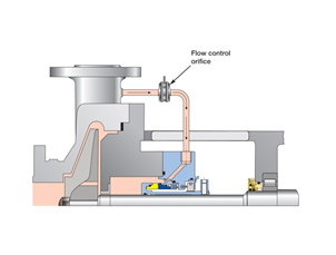
Fig. 3: Recirculating (injecting) a product side stream (API Plan 11)
Recirculation of a product side stream (Plan 11, Figure 3) is common. The side stream should have a pressure of approximately 25 psi (173 kPa) higher than the pressure directly behind the pump impeller.
Axial holes have been drilled in the impeller discs of Figures 3 through 8. The pressure acting behind each particular impeller is thus kept near suction pressure. Drilling several axial holes will also influence the axial thrust produced by an impeller and may affect the load on the thrust bearing set. Recall that Pressure (psi or N/mm^2) = Force /Area; hence, Force = Pressure multiplied by Area. For optimum bearing life, this force cannot be too light (skidding risk) or too large, which after resulting in insufficient oil film strength and thickness would lead to metal-to-metal contact and bearing failure.
RELATED CONTENT: Selecting Flow Control Devices on Plan 11 Piping
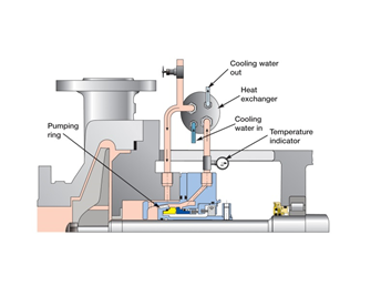
Fig. 4: Product recirculation from seal chamber to heat exchanger and back to seal chamber per API Plan 23
A heat exchanger (Figure 4) adds to the cost of an installation, but may be required in some services. Modern mechanical seals often include an internal pumping device—an important option that will be further explained later in Figure 12.
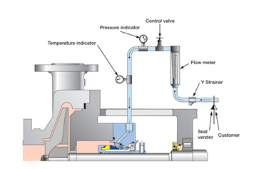
Fig. 5: Injection of cool or clean liquid from external source into the seal chamber per API Plan 32
Some applications favor the flush plan shown in Fig. 5 although, again, its ultimate suitability for a given application or service must be assessed. The liquid injected into the seal cavity will migrate through the throat bushing and into the pumpage. This dilutes the process fluid and the injected fluid will later have to be removed by evaporation. Because evaporative processes require considerable heat the overall energy efficiency of the plant is inadvertently reduced simply because of a particular seal plan selection.
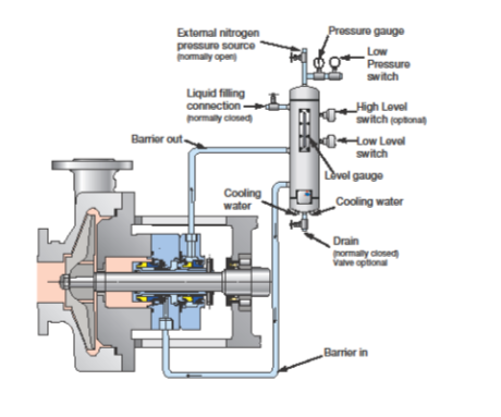
Fig. 6: API Plan 53A—Pressurized barrier fluid circulation in outboard seal of a dual seal configuration. A pumping ring maintains circulation while running; thermosiphon action is in effect at standstill
Dual seals utilize a barrier or buffer fluid to create a desirable seal environment, Fig. 6. The cost of the seal auxiliaries shown here is clearly a factor and each application merits its own review. Connection to an external nitrogen source requires safeguards against the inadvertent backflow of barrier fluid into the external source of nitrogen. The possibility of nitrogen dissolving in the barrier fluid must be considered as well. In other words, seal selection requires considerable study and experience.
Both Figures 7 and 8 are variations on our “go with advanced technology” theme and highlight why it is so important to have good cooperation between seal manufacturer and seal user-operator. Figure 8 (API Plan 62) is schematically shown again in Figure 9; it is important to note that many of these seals and flush plans have been converted to the far more effective water management approach shown in Figure 10.
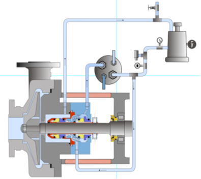
Fig. 7: API Plan 53C—pressurized and cooled barrier fluid circulation in outboard seal of a dual seal configuration. A pumping ring (see later, Fig. 12) maintains circulation while running. The pressure is maintained and fluctuations are compensated in the seal circuit by a piston-type accumulator, upper right.
RELATED CONTENT: Proper Filling of Plan 53C Systems
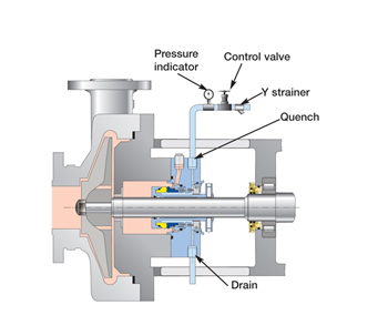
Fig. 8: API Plan 62—an external fluid stream is brought to the atmospheric side of the seal faces using quench and drain connections (This is a very inefficient use of water)
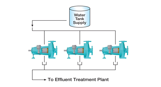
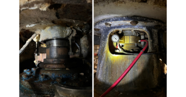
Fig. 9: An energy-inefficient API Plan 62 in use at an older sewage treatment facility
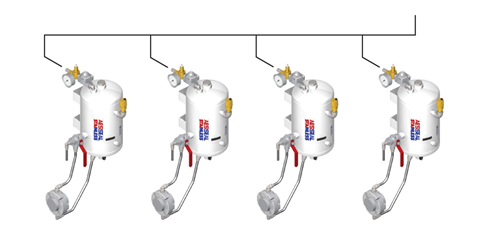
Fig. 10: Four water management systems connect to the seal glands of four separate pumps in this sample illustration. There is no drain and no water is wasted
All flush plans have advantages and disadvantages
The many properties of fluids contacting the seal faces govern seal selection, but other considerations should be weighed as well. Long-term reliability and savings in utilities should be given high priority. Conversely, low initial seal cost is rarely (if ever) a good indicator of the true value of mechanical seals and seal support systems (Ref. 3).
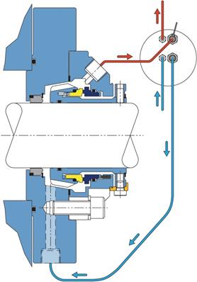
Fig. 11: Plan 23 cross-section of a seal cavity with a bi-directional (tapered) pumping device. The flush product is pumpage that passed through the throat bushing on the left. After being cooled in a heat exchanger (upper right), this product re-enters the seal region in the vicinity of the seal faces. A bi-directional tapered pumping device (see Figure 12) promotes relatively high flow rates and thus cooler face temperatures.
Historically, Plan 23 has not received wide acceptance due to the obvious complications of applying old-style seal circulating devices or pumping rings. Utilization of modern computer-controlled manufacturing methods has helped implementing superior sealing technology.
Compact Plan 23 cartridge seals (Figure 11) are easily applied to both new and old pumps. These seals incorporate wide-clearance bi-directional tapered pumping devices that are far less likely to make contact with seal-internal stationary parts than older, close-clearance pumping ring configurations.
Always obtain the full picture
Seals are part of a pumping system and systems must be properly reviewed. This is demonstrated with API Plan 23, see Figure 11. The reviewer must first recognize that the seal assembly incorporates a throat bushing which will almost (but not fully) isolate the seal chamber from the pump’s case. The small volume of liquid in the seal chamber is circulated through a local cooler. API Plan 23 is used on hot applications and minimizes the load on the heat exchanger. It needs to cool only the heat generated by the seal faces and the heat that has migrated through the seal chamber casing. An effective pumping or circulating device (Figure 12) is at the very heart of Plan 23.
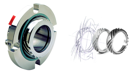
Fig. 12: A bi-directional tapered pumping ring assembled (left) and shown separate (right)
Seal chamber pumping ring (circulating device) technologies
Many of the pumping rings found in mechanical seals are based on a straight vane or paddle-type configuration (Figure 13). Typical pump-around flow rates achieved with traditional pumping rings are quite low. They will function only in the plane where the ports and the straight vanes (paddles) are located. Tangential porting will be required and in many instances little or no liquid is induced to flow continually over the seal faces.
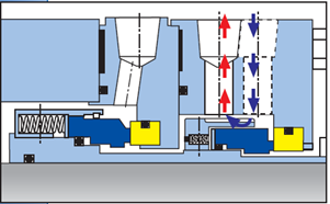
Fig. 13: A relatively ineffective straight-vane pumping ring
Pumping screws (Figure 14) are considerably more efficient; however, they must rely on a dimensionally close clearance gap between screw periphery and housing bore. This close gap can be a serious liability in situations where shaft deflection or concentricity issues exist. Designs with a close gap will not comply with the API 682 (2002) requirement of a minimum radial clearance of 1.5 mm (0.060”). But screw devices with large clearance gaps (Figure 14) have poor efficiency and can be as ineffective as the straight-vane pumping rings of Figure 13.
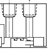
Fig. 14: Pumping screw found in some dual seals. To be effective these auger-type helical screws will require close clearances, but close clearances introduce risk factors
Traditional pumping screws (Figure 14) are, of course, unidirectional. This inherent uni-directionality leaves ample opportunity for human error on between-bearing pumps; recall that left-hand devices are required on one end and right-hand devices on the other end of the shaft.
Close radial clearances between counter-rotating surfaces can lead to component contact and galling. If a stainless steel rotary component contacts a stainless steel stationary component, galling will occur.
Some dual seals applied in industry are designed with radial clearances in the order of 0.010” and 0.020” (0.25 mm and 0.5 mm). This contradicts best-practice guidelines and technical logic because pumps operating away from BEP (“Best Efficiency Point”) and most single volute pumps are known to undergo a measure of shaft deflection.
Whenever the dual seal radial clearance is less than the throat bushing clearance in the pump, a close-clearance helical screw device will be the first to make contact. All these potential issues are avoided with open-clearance bi-directional tapered pumping rings (Refs. 2 and 3).
Lessons apply to many services
We chose here to summarize the seal topic by using a few schematic representations. In one particular API Flush Plan explained in Refs. 2 and 3, process fluid is diverted from the discharge of the pump, sent through a restriction orifice and a seal flush cooler, and then routed into the seal chamber. The seal flush cooler is removing heat from the process stream. If the production process demands a hot fluid, such heat removal will benefit only the seal. In that case, cooling the flush stream would reduce the overall process energy efficiency.
References
- Bloch, Heinz P. and Allan Budris; “Pump User’s Handbook: Life Extension,” 4th Edition, (2014), Fairmont Publishing, Lilburn, GA, ISBN 0-88173-720-8
- Bloch, Heinz P.; “Pump Wisdom: Problem Solving for Operators and Specialists”; (2011), Wiley & Sons, Hoboken, NJ; ISBN 9-781118-04123-9
- Bloch, Heinz P.; “Petrochemical Machinery Insights,” (2016) Elsevier Publishing, Oxford, UK, and Cambridge, MA, ISBN 978-0-12-809272-9