Author: Randal Ferman
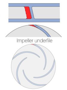
Underfiling is the removal of material from the underside (also back side, “non-working” side, or suction side) of an impeller vane at the inlet or the exit. In this article, underfiling will refer to the exit. The terms “underfiling”, “back-filing”, “S2cutting”, and “Sv cutting” are equivalent. There are probably others. A related term is “overfiling” which refers to material removal from the top-side or “working” side of the vane. By the way, I’m not a stickler for proper punctuation – I prefer “underfile”, but purists are inclined to use “under-file” with a hyphen.
Pump manufacturers routinely underfile cast metal impellers. Impeller underfiling is primarily a means ofestablishing dimensional uniformity at the vane exit tips. Vane-to-vane uniformity, in turn, reduces variation in performance from one pump to the next.
Underfiling also “straightens” the vane outer diameter surface or “land”. Conventional low production volume sand casting processes usually require a vane shape that tapers from a thicker section at the impeller hub side to a thinner section at the eye shroud side. Additionally, any other vane-to-vane or vane thickness non-uniformity may show up in the finish machined land as an irregularity. An underfile procedure straightens the vane lands to parallel edges.
An impeller with nicely shaped inlet and exit tips, cleanly ground cast surfaces and uniformly machined features
has a certain aesthetic appeal. It may or may not affect its performance, but it certainly affects emotional attitude.
Some manufacturers do not underfile, except when needed after a performance test. High volume production impellers are often cast, fabricated, or molded with dimensional precision and the need for underfiling is eliminated.
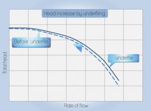
Underfiling is also used to increase the pump head versus flow (H-Q) performance. This can be thought of as either increasing head or increasing flow. The potential for increasing head can be in the range of a few percent to as much as 10%. Underfiling or overfiling may also bump up the pump efficiency a bit – usually not more than 0.5%.
The initial underfile process removes sufficient material to ensure that all vanes are underfiled uniformly. Usually there is opportunity to remove additional material and achieve a new underfile condition. This is useful if some additional H-Q performance is necessary after test or when the slope of the head rise-to-shutoff needs to be “flattened” through a combination of underfiling and trimming. A variety of vane exit geometry modifications are used for performance adjustment.
Predicting the outcome of a given underfile can be accomplished analytically or by using historical test data and experience. Some impeller designs will not respond well to underfiling in terms of increasing head. CFD calculations may be warranted for high consequence applications. A calculation procedure based on the Euler equation for head, an estimate of the impeller hydraulic “slip factor”, and details of the impeller underfile geometry can be used to bracket the upper and lower bounds of the expected change in head. However, lacking prior experience with a given pump geometry, the analytical prediction should be considered as an informed engineering guess. This is especially true when the underfile is accompanied by other hydraulic modifications.
In theory, impeller vanes could be underfiled to knife edge thickness. This is not at all practical as the thin vane sections will quickly erode away or break off in service. Also, thinning down the vanes to a small fraction of their original thickness may result in fatigue breakage at the impeller exit. Apart from mechanical considerations there are diminishing returns in H-Q performance from thinning down vanes. The practical limit of underfile thickness reduction should take into account the (head x density), the vane number and knowledge of the design’s susceptibility to fatigue failure for the given application.
The vane exit tips on high head impellers, such as found in boiler feed pumps and other high pressure services, may be filed to an elliptical tip shape to reduce stress concentrations. Such an operation normally involves material removal from both top and under sides of the vane. Careful attention is also given to the vane-to-shroud fillet radii.
Underfiling is a manual procedure. It involves careful layout and skillful grinding. Templates are often used. On engineered impellers, underfiling is usually performed by tradesmen possessing substantial experience in these procedures.
While not all impellers are underfiled, the procedure certainly plays an important role in the manufacturing of engineered-to-order or assembled-to-order industrial pumps. The technologies in support of underfiling range from shop grinding to CFD engineering.
For an independent evaluation of pump impeller trimming and underfiling, contact an experienced consulting engineer who can help with your specific application.


