In his analysis, Dave Allard from Hydro, Inc., USA, investigates the underlying factors behind unexplained vibration in a troublesome pump used for transferring urea ammonium nitrate solution. Through a meticulous examination, he not only identifies the root cause but also offers a lasting remedy by implementing a range of engineered upgrades and a thorough modification of the thrust bearing.
A recently constructed fertilizer plant was experiencing significant vibration problems on their brand new urea ammonium nitrate (UAN) solution pumps. This vibration forced the plant to take the equipment out of service.
The site was unable to diagnose the root cause of this problem and the unreliability and resulting unavailability of this critical equipment was causing significant stress on the new plant. The company heard through another fertilizer plant that a global aftermarket pump service provider had been able to diagnose and remediate their pump problems with success. The site reached out to this aftermarket pump service provider to help identify the issue and provide solutions.
The pump was shipped to the provider’s repair shop to perform a thorough disassembly, cleaning, and inspection (DCI). The engineering team reviewed the original pump design and historical vibration information provided by the plant. Between this review and the DCI results, sufficient evidence was gathered to perform a root cause analysis (RCA) that explained the aberrant behaviour of the problem pumps. The pumps were then re-engineered to remove the diagnosed problem and provide the plant with reliable operation.
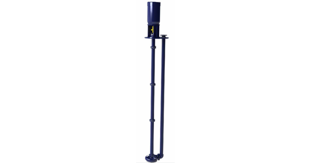
Typical VS4 pump configuration
Background
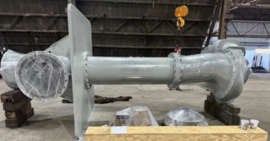
The UAN solution pumps are formed of a single stage VS4 vertically suspended pump design and are installed in a process condensate tank. The pump is submerged in the UAN solution and takes suction through an axial suction nozzle equipped with a suction strainer.
The pump has a radial discharge nozzle located at the impeller centreline; this discharge continues through an elbow to a length of vertical pipe that exits the process condensate tank.
Above the impeller, a series of column pipes and lineshafts connect the hydraulic assembly to the motor assembly located on the tank top flange. The lineshafts are supported by three guide bushings located in column spiders.
The impeller was designed with back rings and balance holes to greatly reduce the total axial down thrust of the pump. Calculations show that the hydraulically generated down thrust is very low and almost all of the axial thrust is attributed to the static weight of the rotor.
Because of particulate in the fluid, the bushings are provided with a clean lubricating flush. The flush line is taken off the discharge line and runs through a cyclone separator. It is then injected through ports at each bushing location.
The high vibration observed at the site was accompanied by abnormal noise at the pump, usually indicative of either looseness or broken parts. The site communicated that extensive damage to the pump had been observed on a previous refurbishment.
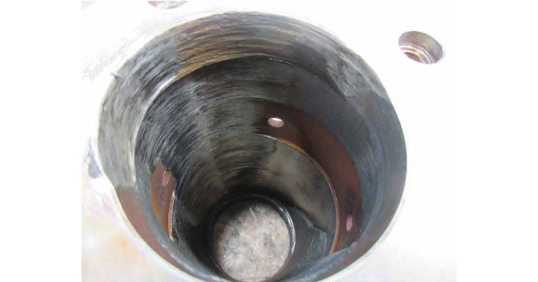
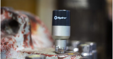
Heavy wear of bushing bore
The evidence
When the pump was disassembled, it was evident that there were significant problems at the motor bearing and guide bushing locations. The motor ball bearing cage had become unseated and was damaged. Inspection of the mechanical seal revealed damage to the sealing faces.
The DCI also revealed elliptical wear on the guide bushing bores that was biased to one side, indicating a misalignment problem. Galling was observed at the impeller and case rings. Dimensional analysis of the components revealed major excursions from recommended tolerances, including:
- Excessive runout of the motor stand faces – runout was measured at 0.018 in. and should be a maximum of 0.002 in.
- Excessive clearance at the motor stand register to the baseplate – clearance was 0.015 in. and should be a maximum of 0.002 in.
- Motor flange face runout was 0.003 in., outside of the recommended maximum tolerance of 0.002 in.
- Lineshaft coupling tolerances were specified to a substandard class and resulted in excessive runout.
- Column spiders that hold the guide bushings had excessive fit-ups at the registers and face runout, bore concentricity, and other tolerances were all outside of recommended maximum values.
- Site inspection of the sole plate revealed that it was not level.
The aftermarket pump service provider performed a RCA that took into consideration the DCI results, original pump design, vibration spectra, and operating conditions to reveal the likely causes of degradation. Issues identified by the RCA included:
- The motor coupling was the incorrect design.
- The guide bushing bores were running against the lineshaft couplings instead of the shaft or a shaft sleeve.
- The flush line could be optimised to provide the guide bushings with cleaner fluid.
- Excessive manufacturing tolerances and clearances led to misalignment of the rotor and non-centreline compatibility of the stationary wear component bores.
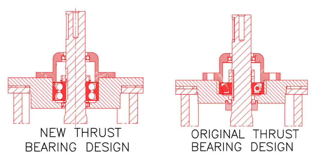
The high vibration and abnormal noise that caused the pump to be taken out of service was most likely due to the poor motor thrust bearing design. The original thrust bearing selected by the OEM was a single row angular contact bearing. This bearing was only capable of handling thrust in one direction.
It is suspected that the pump experienced a momentary upthrust upon start-up, resulting in the unseating of the bearing cage. This unseated bearing was unable to function properly even as the pump reached its normal operating thrust. Because the bearing did not restrain the rotor in the upward direction, the rotor movement caused by the upthrust resulted in contact and damage at the mechanical seal axial sealing faces.
Another contributing cause to the high vibration was the contact and wear at the guide bushing and case ring bores. This wear was caused by several factors, the greatest of which was a design flaw that placed the lineshaft coupling under the guide bushing bore. Poor component tolerances, misalignment, and subpar work done by the contractors during initial installation, including sole plate runout and probable pipe strain problems, also contributed to the contact and wear.
It is highly unusual for a lineshaft coupling to be located under a guide bushing. Most lineshaft couplings are located above the bushing location for two reasons: couplings are areas where runout is more likely to occur and locating the coupling above the bushing provides greater ease of lineshaft disassembly.
Solutions
The aftermarket pump service provider used its engineering team to redesign the pump and remove the design flaws that caused high vibration, accelerated wear, and poor reliability.
 In addition to refurbishing or replacing the damaged parts and providing a new mechanical seal, five major changes were implemented:
- The single row angular contact motor thrust bearing was replaced by a double-row deep groove ball bearing
- The lineshaft coupling location was moved to above the guide bushing area. Shaft sleeves were manufactured and installed to run against the bushing bore
- All bushings were designed to have a spiral groove that would help flush any particulate still present in the lubricating flush out of the bushing bore
- Component tolerances were significantly tightened to ensure better centerline compatibility of stationary parts and to reduce the probability of misalignment
The double row deep groove ball bearing that was chosen to replace the angular contact bearing is able to handle axial loads in either direction and will not be at risk of unseating due to axial upthrust. This bearing design will also protect the mechanical seal by restricting rotor axial movement in both directions. In order to accommodate the new bearing, the bearing housing was modified.
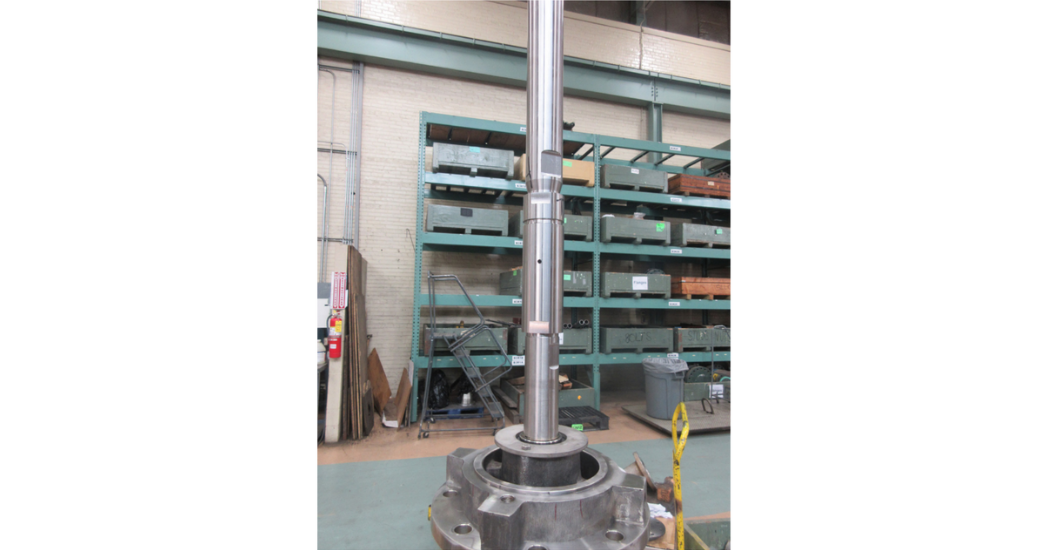
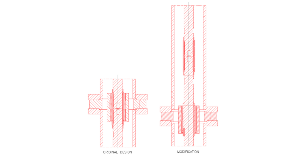 To relocate the lineshaft couplings away from the guide bushing location, the impeller shaft length was increased from 12” to 14”. The intermediate shaft length was kept the same and the head shaft was reduced by 2” to maintain the same total rotor length. Additionally, shaft sleeves were installed at the guide bushing location to protect the shaft and maintain the design clearance to the guide bushing.
The column spiders were machined to provide better tolerances with the intention of reducing the possibility of misalignment caused by non-concentricity of the bearing bores relative to the rotor centerline. While machining the spiders, dimensions were standardized to ensure that these components could be interchangeable in the future.
The Results
The redesign required modifications to ~70% of the pump. With one pump removed for service, the site was forced to operate with only one pump. As such, these modifications needed to be completed on an emergency schedule. Fortunately, the aftermarket pump service provider had the resources to perform this repair on the required schedule of 2-3 weeks, allowing this piece of critical equipment to return to service.
The new pump design has resulted in successful operation since installation and start-up in late 2017.
Originally published in World Fertilizer’s July/August 2020 issue.