A common issue when diagnosing pumps and motors is excessive current draw. There are many causes of high current, such as worn components, operating far to the right of the performance curve, or nuisance ragging of the impeller. While these sources of high amps are focused on the pump performance, an often-overlooked source is from the electrical power supply.
Electric motors are designed to operate within a tolerance of voltage from the nameplate. NEMA defines this tolerance as +- 10% of the nameplate voltage. However, that tolerance is only applicable when all 3 phases of the supply are providing the same voltage. If the phases are providing unbalanced voltages, this will result in an unbalanced current draw between the phases and will result in a higher than expected amp draw. While a motor can successfully operate at +- 10% of nameplate voltage, even a small voltage unbalance of 1% can lead to a measurable current increase.
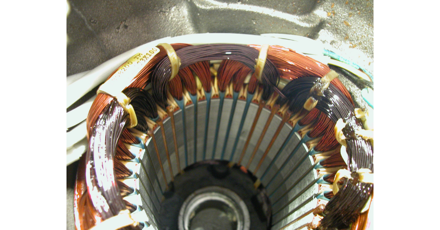
NEMA describes the current imbalance as between 6-10 times the measured voltage unbalance. To further the problem, some of this excessively high current is in the form of circulating currents within the stator, and therefore is not readable at the control box. The generation of these circulating currents is best defined as follows:
From NEMA MG-1 part14, Page 11
“The effect of imbalanced voltages on polyphase induction motors is equivalent to the introduction of a “negative sequence voltage” having a rotation opposite to that occurring with the balanced voltages. This negative sequence voltage produces in the air gap a flux rotating against the rotation of the rotor, tending to produce high currents. A small negative sequence voltage may produce in the windings currents considerably in excess of those present under balanced conditions.”
Temperature rise within the stator windings will be proportional to the actual (not measured) current imbalance. The increased heat should cause the winding thermal sensors to react and shut down the motor when the windings reach a preset temperature, provided the thermal sensors are properly wired and the alarm is not overridden. However, continued operation of the motor at elevated temperatures will lead to a breakdown of the winding insulation. In addition, continued cyclic operation of thermal switches will cause decay of their set temperature, and may ultimately lead to their failure.
While the voltage imbalance has a considerable effect on the stator winding, problems will also arise within the shaft/rotor assembly. Induced circulating current will cause the rotor to heat up. This may cause the rotor to expand, and excessive heat will be directly transferred to the motor bearings and mechanical seals through the shaft.
Measured current imbalance should not exceed (5%), and is generally due to voltage imbalance in the supply. To determine if the imbalance is coming from the load or the source, use the following procedure.
- Measure and record the voltage on each power lead. (L 1, L 2, L 3 )
- Change all three power leads as follows: L 1 to L 2, L 2 to L 3, L 3 to L 1.
- Measure and record voltage on each lead again. (L 1, L 2, L 3 )
- If the imbalanced leg follows the motor lead, then a problem exists somewhere within the pump cable, connections, or stator winding.
- If the imbalanced leg stays on the same control box terminal and jumps to a different pump lead number, then the problem is with the supply or control box.
If the voltage imbalance is found to be with the supply, then it must be:
- Corrected by inspection and repair control box wiring or components.
- Corrected by working with the power company.
- Reduced by decreasing the load on the motor.
- Compensated for with an oversized motor to handle the additional heat energy.
A voltage imbalance will cause additional heat buildup within the motor. The degree of problems and/or damage will be a function of the voltage imbalance and the load factor of the motor.
As a minimum, nuisance thermal tripping will occur. If this goes unchecked, the following mechanical damage may occur.
Bearings – Grease will be melted out of the upper bearing. The bearing will often look dry.
Stator – Winding insulation will breakdown, ultimately causing a short in the winding.
Rotor – May expand enough to contact the stator assembly. Will often be blue in color due to the heat.
Upper Mechanical Seal – Elastomers will be hard and brittle from heat exposure. Seal faces will often have heat checking them.
Continued operation of any pump with a significant (over 1%) voltage imbalance will make the above list of damage a certainty at some point in the motor’s life.