Contributor: Europump
Introduction
Various countries around the world have taken different approaches towards energy usage and possible energy reduction. Across Europe, the Commission has concentrated on components within the Energy Related Products Directive (ErP).
The ErP focuses heavily on the efficiency of the products and the Commission has already implemented legislation to ensure that products with low efficiency are gradually phased out across Europe. A significant step in the right direction for sure, although new ‘energy efficient’ components may still be required to operate within an inefficient system, impacting hugely on any possible efficiency gains.
To evaluate the energy efficiency of a pumping system takes time, knowledge, and the will by both the pump system energy auditor and the pump’s operator (customer) to make a determined change. But the rewards are most definitely worth the effort. The potential energy savings throughout Europe are estimated at being between 40-50 TWh if the necessary changes to inefficient pumping systems are made.
The Systems Approach
First, let us define what we mean by a system.
A pumping system is defined as one or more pumps and those interacting or interrelating elements that together accomplish the desired task of moving a liquid. A pumping system generally includes pump(s), driver, drives, distribution piping, valves, controls, instrumentation, and end-use equipment such as heat exchangers. Using the ‘systems approach’ involves comparing the need or demand to the supply.
It is important to understand how the different components in a system interact and influence each other. A change to one component might improve or negatively impact other components.
An example of this is replacing an old inefficient motor that is employed to drive a pump, with a modern high-efficiency motor. The newer high-efficiency motor will have less slip and will run faster than the old motor. When the pump is running faster, it will consume more energy and this increase in energy usage can be larger than the savings produced by the more efficient motor. To reap optimum savings from the change, the pump impeller might have to be trimmed.
A system approach starts with defining the ’ultimate goal’ of the system. This includes determining the flow rates that the system must be able to deliver, whether there are flow variations and what kind of control is necessary. These requirements will influence the choice of piping size, control methods, pump size, motor size, and so on.
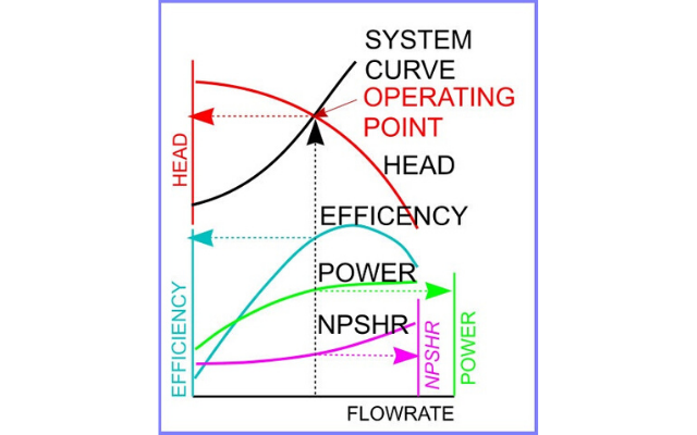
Figure 1 uses the pump and system performance curves to determine pump operating conditions and to evaluate methods of flow control.
To determine the efficiency of a system, the minimum energy to fulfill the process demand is compared to the actual energy used. Figure 2 illustrates the difference between looking at components and looking at systems. The diagram shows a remarkably simple system pumping a liquid from one tank to another. When looking on a component perspective we compare the input power to the motor from the MCC to the liquid output from the purple square around the motor and the pump. This analysis could indeed yield an excellent result. If we broaden the view a bit, we can see a re-circulating line going back to the first tank. The flow rate coming out of the purple square in is hence smaller than in green square. The power input is however the same.
Finally, we take a complete system view and include the losses in the recirculation line as well as the losses in the regulating valve on the line to the second tank. What might have looked as a reasonably good system on the components in the purple square can be viewed as an extremely low-efficiency system when looked at using the systems approach illustrated by the red outline.
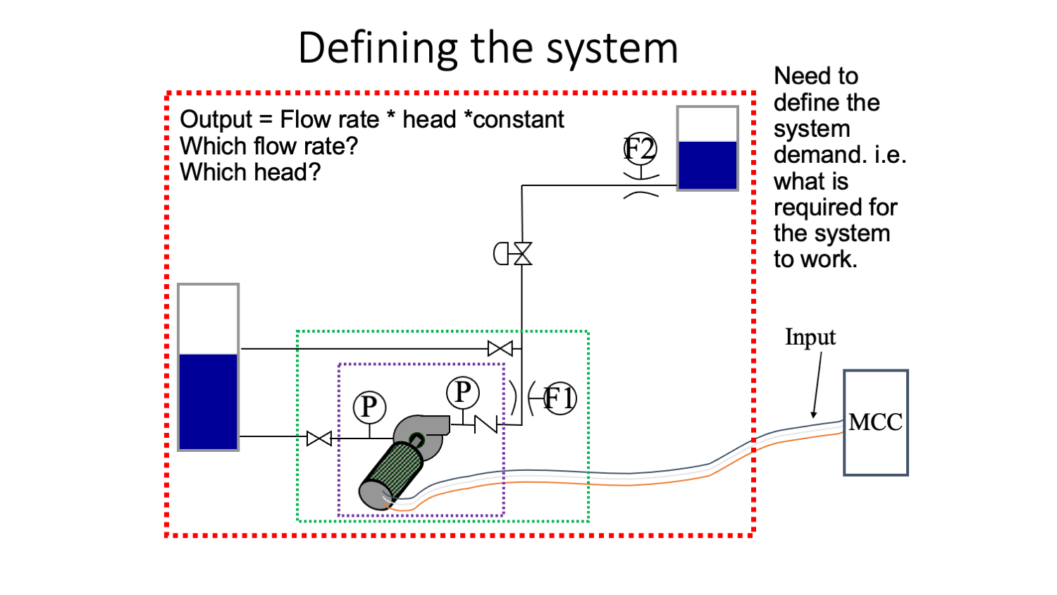
Fig. 2 Efficiency of a pump measured on a component basis (purple box) based
the ratio between input and output indicated by the purple box. The system view
includes a re-circulation line as shown by the green box. Looking at the complete
pumping system using a total system approach is illustrated by the red box
To do this we need to define the system demand, i.e. the minimum pressure, flow rate, and subsequent energy for the pumping system to work. To understand the knowledge and tools required to assess the system, industry spent many years developing the international standard ISO 14414 – Pump System Energy Assessment.
Conclusion
There are many exciting energy use improvement programs being developed around the world, but in Europe, we have the Energy Efficiency Directive which mandates energy audits in Systems. For the electrical energy savings identified in pumping systems to be fully achieved, there needs to be a far stronger emphasis on the ‘systems approach’ and a commitment to make this happen from both the pump industry and its final end users – those that will ultimately benefit from lower energy bills.
Europump would like to thank Steve Schofield, CEO, British Pump Manufacturers’ Association for his help in compiling this article.
For further information on the work undertaken by Europump, please visit the website – www.europump.org – or contact its Secretary-General, Pierre Lucas, via email at pierre.lucas@orgalim.eu .
https://empoweringpumps.com/europump-extended-product-directive-a-pump-is-not-a-light-bulb/

Comments