In the mid-1990s, a gas production facility in Colorado sought new technology for regular seal changes on its 6000 hp (4474 kW) fleet of screw compressors requiring regular seal changes. The search began because of dissatisfaction with the process then in use.
For example, in order to access the seals, the coupling and the coupling hub had to be removed from the compressor shaft. Also, the hub size and equipment location made for a difficult removal of the shrunk-on keyed hubs. And because open flame heat was required to remove and reinstall the hub when changing seals, hot-work permits were a necessity. Furthermore, repeated heating of the hubs gradually deformed and ruined the hubs.
The solution the operator sought would permit easy installation and removal for the hubs without the use of heat. In response to that desire, Couplings Corp. of America (CCA) designed and installed a new keyless hub with a mechanical interference fit. The new hubs allowed easy axial shaft positioning, and installation required only hand tools. The first hub was installed in 1997 and hubs were later installed on the remaining compressors.
Before the first hub was installed, it underwent a mechanical test to prove its torque carrying capability. After being subjected to five times its rated torque, the test was halted for safety reasons.
Since its original use, this keyless device has been used in many different applications including gas turbines, pumps, fans, ship propulsion, and even wind turbine drives.
Many of these applications have nominal torques in excess of 1 million lb.in. (113,000 Nm). There is one place, however, where users had been reluctant to try this device — large reciprocating compressors. Many potential users had been concerned about the sizable torque spikes in that type of application, and they determined that the risk was too great on that size equipment.
In 2006, a gas producer in Alberta, Canada, was experiencing disc coupling failures on some 1900 hp (1417 kW) motor-driven reciprocating gas compressors. They hired Beta Machinery Analysis in Calgary, Alberta, to help them determine the cause of the failure. Beta determined that the torsional stiffness should be changed to avoid some torsional resonance in the system. The easiest way for them to make this change was to increase the size of the current coupling.
Meanwhile, the Calgary-based packager who sold the systems elected to try a clamping hub in conjunction with the new coupling. The packager, working together with a local distribution and engineering group, presented the idea to the end user. Despite their higher initial cost, the operator recognized the possibility of potential future savings in maintenance.
CCA designed clamp hubs for the application, and the flange of the hub was made to match the bolt circle of the disc coupling. The compressor shaft size was 6.75 in. (17.15 cm) and the motor shaft size was 6.3 in. (16.0 cm). The motor was rated at 1900 hp (1417 kW) at 1200 rpm, for a nominal torque of about 100,000 lb.in. (11,300 Nm). Because of the severity of the application, the service factor was at least three. Coupled with the need to increase the size of the coupling for torsional reasons, the service factor was elevated even further.
The eventual torque rating of the disc coupling was 813,780 lb.in. (91,940 Nm), with a peak capacity of 976,536 lb.in. (101,030 Nm). Therefore, the clamp hubs were designed to match the torque capability of the coupling. The peak torque capacity of the clamp hub was 1.63 million lb.in. (184,165 Nm), or double the normal torque capability. Eventually, the hubs were joined with the spacer and discs in Calgary before heading to the plant site.
Removing the existing hub required heating, pulling and grinding to remove it from the shaft. The process took approximately 24 hours and resulted in a gouge at the end of the shaft.
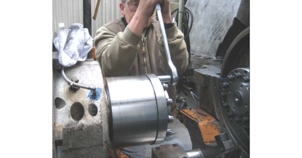
Mechanic installing an Anderson Clamp Hub with a low-profile flange on a 6 in. (1.52 cm) tapered shaft.
The clamp hub was slid onto the shaft with about 0.001 in. (0.254 mm) clearance between shaft and hub bore. The hub slid over the gouged part of the shaft without any problems. From crate to complete installation on the shaft — and even though the mechanics doing the work were unfamiliar with the new design — the job took only about 75 minutes. With experience gained from that first installation, succeeding units took even less installation time.
Two weeks after the initial installation, the plant operators realized that the hub on the motor needed to be moved slightly to accommodate a different magnetic center. This process required removal and reinstallation of the hub. The design of the clamp hub helped shorten that process by over a day, saving the plant about US$22,000 in lost production and easily recovering their cost.
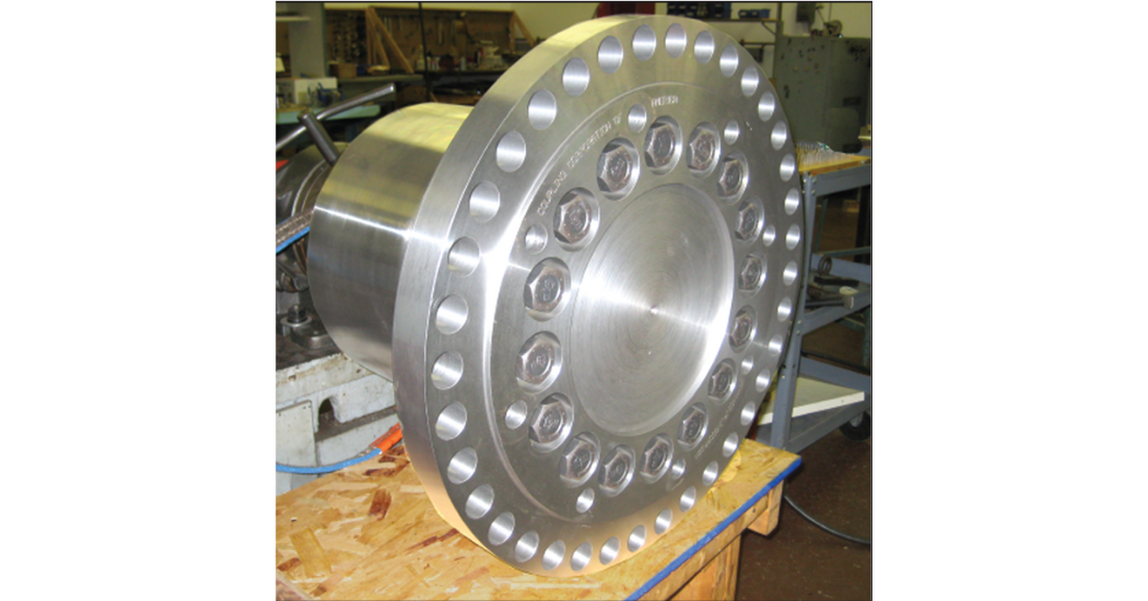
The concept of the clamp hub is simple. There are two main pieces, the hub body and the collar, both manufactured from hardened alloy steel. The hub body has a regular hub flange and a thinner sleeve section that is partially slit. The hub body is bored to match the shaft, either straight or tapered. CCA explained that the collar screws onto the outside of the sleeve section of the hub body using a patented asymmetric thread until it touches the back of the hub flange. At that point, the collar comes into contact with a set of load screws in the hub flange.
 Once axial positioning of the hub is correctly tightened, the loading screws push the collar away from the hub flange. The more the collar is pushed, the more pressure is built up in the threaded interface between the collar and hub. The thickness of the collar resists the internal expanding forces, and the pressure is translated into interference between the hub and the shaft.
In order to determine how tight the hub is on the shaft, CCA utilizes a specific procedure. Depending on the difference between the hub bore and the shaft diameter, there could be diametrical clearance between them of up to about 0.002 in. (0.0508 mm). Obviously, the tightening procedure needs to take into account any amount of clearance between hub and shaft.
The first step of the process is to tighten each loading screw approximately a quarter turn in a sequential pattern rather than a standard star pattern. Once the pattern of loading screws has been tightened once, the torque capability of the hub is tested by twisting it by hand on the shaft. If it slips on the shaft, the loading Starting gap A screws should get one more round of tightening, and the process repeats until the hub cannot be moved by hand.
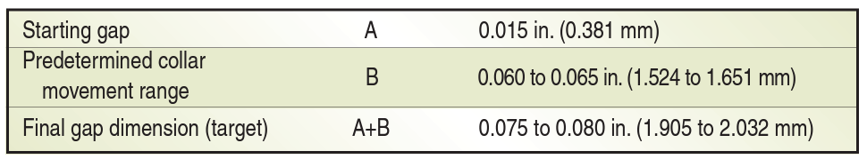
Once the hub has reached this state, the small gap between the collar and the hub flange can be measured with a feeler gauge. The first measurement is considered the “starting gap.” For every specific hub size, a predetermined collar movement is needed to achieve the correct pressure between the hub and the shaft. The amount of the movement is usually between 0.02 in. (0.508 mm) and 0.1 in. (2.54 mm), depending on the size of the hub and the shaft.
The amount of movement is also given as a range, where the lower value is the minimum movement needed. By adding the starting gap amount to the predetermined collar movement amount, the final gap amount is determined. Here is an example of how the numbers are used:
Knowing the final dimension target, the loading screws can begin to be tightened using the same sequential process. The collar should move approximately 0.002 in. (0.0508 mm) for each complete pass of the loading screws. Once the final gap dimension is reached, the hub is ready to handle the designated torque.
For removal, the process is basically identical except in reverse. The loading screws are loosened sequentially with very small movements. Once the collar has retreated to its original position, the hub should be loose on the shaft. In the case of the collar getting stuck in the tight position, the hub is equipped with three puller holes along with a lip on the OD of the collar. By placing the bolt heads over the collar lip, the other ends of the bolts protrude from the hub face, and then nuts can be used to pull the collar back to its original position.
According to CCA, the mechanical shaft/hub interference created by the clamp hub is usually significantly larger than that of a heat-shrunk hub. A normal interference for a heatshrunk hub could be between 0.0005 and 0.002 in. per inch of shaft diameter (0.0323 and 0.1290 mm per cm of shaft diameter), depending on several factors, including whether or not there is a keyway. A typical interference using the clamp hub is 0.002 to 0.004 in. per inch of shaft diameter (0.1290 to 0.2581 mm per cm of shaft diameter), although that number can change depending on the situation.
In terms of the torque rating for the hub compared to other hubs, a similar methodology is used. Usually, the hub is rated for the same nominal torque value as the rest of the coupling. In most cases, however, the hub should not be the weakest point of the complete coupling. The flexible element should be designed to fail before the hub slips on the shaft. Therefore, even though the hub has the same nominal rating as the rest of the coupling, it has a higher safety factor. In a typical application, the clamping hub can be expected to carry four to five times the nominal application torque before slipping.
The hubs were installed in April of 2007 and the compressors have been running for the majority of time since then, CCA reported. The end-user has purchased more hubs for similar applications despite their premium price based on savings realized by reduced maintenance expense. Because hotwork permits are not needed, the hub service does not require unnecessary shutdown of adjacent equipment for safety reasons.
CCA said other benefits of using the clamp hub arethe elimination of shaft damage from heat-shrunk hub removal and installation, the ability to remove hubs with simple tools and without the need to ship a compressor shaft to a shop to have the hub removed, which is especially beneficial for remotely located units.
Originally published in CompressorTECH²