In my last blog I defined some of the more common coating types used as protective barrier or wear resistant systems. Assuming you have evaluated your conditions of exposure, and have done due diligence in the selection of a suitable system, you are now tasked to properly apply the coating system to achieve successful results. Several areas of importance should be noted here to insure this and avoid pump system upsets.
To achieve pump efficiencies, critical tolerances of the pump system need to be identified prior to coating. When coating an end suction centrifugal pump, tolerances between the impeller to volute section and the impeller to back plate section are most critical. Depending on the pump type, tolerances can be as little as 0.005”-.008” for typical ANSI pumps. When you introduce a coating, with a film thickness approaching of .015” into a pump with an impeller clearance of .030” (50% of the critical tolerance) you are introducing a potential for higher frictional energy build-up. This can impact the pumps thermodynamic operating parameters. You want to determine how you can retain the optimum clearance specified by the pump OEM. It may be possible to back the impeller off to compensate for the applied coating thickness, or alternatively, to trim the impeller back or machine undercut the casing to create a clearance gap to be made back up by the applied coating itself. Prior to applying a coating system, you have to consider the coatings applied thickness on pump clearances. Make sure the applicator is aware of the critical clearances so you don’t end up with a coating applied at a thickness which renders the pump inoperable. In slurry pumps, critical tolerances also apply however the tolerances may be significantly wider to allow for passage of slurry media. Where tolerances at the back plate to an expeller is required to reduce solids entry into a stuffing box you may have to back the impeller off the plate to allow for coating thicknesses.
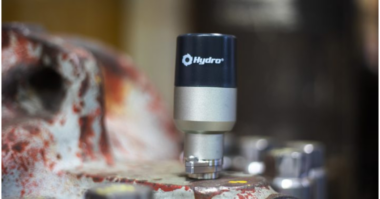
These issues are important, both when coating new pumps and when rebuilding a worn pump. The pump curve on a worn pump may be significantly improved by rebuilding/repairing with coating materials however replacement with OEM spare parts will certainly allow for return to near or as new performance. Consideration of the costs associated with lead times for spare parts, expected downtime associated with the wait for and installation of the repair parts versus rebuilding and coating should factor into your final decision. If you take a worn pump such as shown in figure 1,
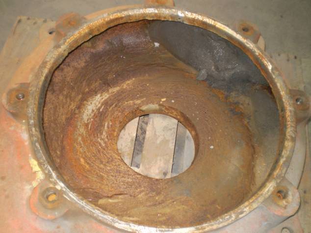 Figure 1
and replacement costs are $4-5,000.00 with lead times of 3-4 week, and compare that with rebuilding and coating which can be accomplished within 3-4 days, the typical costs are usually 30-40% of the replacement part cost. This cost/benefit calculation is important to consider. If the repaired part yields an equivalent lifetime and the asset is being protected against further wear then the capital investment is protected and the financial justification to proceed is positive. Even if the repaired part lasts 75% of the original life of the new part, if the associated down time is reduced and production is maintained then you can still have a positive justification.
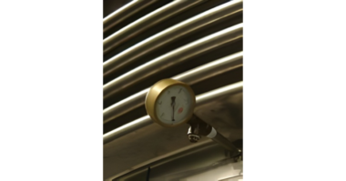
When a worn part is taken out of service for coating (rebuilding to tolerance and protection against future abrasion or erosion/corrosion) there are several critical steps which must be considered to ensure optimum longevity. After disassembly decontamination of the part is very important to remove any surface or imbedded contaminants which could inhibit or reduce adhesion to the substrate. Dissolved salts in porous castings can dramatically reduce coating life due to the osmotic effects of residual chlorides. These “salts” on the surface actually absorb moisture much the same way salt cakes up in a salt shaker on a humid day. Moisture in the form of vapor can be drawn through a coating film by salts leading to the formation of highly conductive electrolytic solutions on the steel leading to galvanic corrosion so removal of them by high pressure fresh water washing is always the first step. Likewise acidic or caustic contaminants should be removed to prevent adverse chemical reactions with an applied coating. Figure 2 shows a pump parts being pressure washed to remove contaminants.

Figure 2
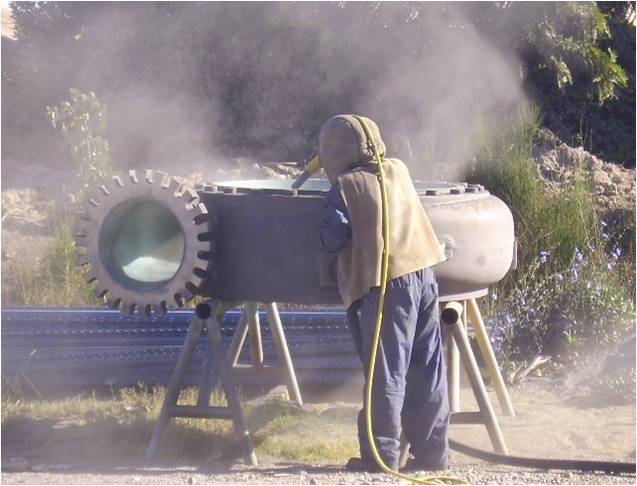
If the rotating element is to be coated then dynamic balancing is recommended and proper balancing protocols carried out. After a surface is deemed free of contaminants the next step is surface profiling to provide a clean and rough surface with a suitable anchor pattern to promote adhesion. This is commonly done by abrasive grit blasting but may be accomplished by power tool as well. Normally a profile of greater than .002” is required for films greater than .010” final dry film thickness. Proper containment and safety protocols should be utilized in this step to avoid airborne escape of abrasives and inhalation of dust and debris. Figure 3 shows a typical abrasive blasting operation. At this stage any machined tolerance area should be masked with a protective covering to avoid damaging the machine finish. Once the surface is inspected for the appropriate level cleanliness and roughness and proper environmental conditions, such as air and surface temperatures, humidity and dew point calculations are established coating can commence.

Figure 3
If rebuilding is required for resurfacing of areas where pitting or erosive wear has been noted, then the use of either weld overlay or a resurfacing/faring compound may be selected. Weld overlay will require subsequent roughening while many faring compounds may be incorporated directly into the overall coating process. Figure 4 shows a “hand lay-up” resurfacing approach using an epoxy based faring compound to localized areas of metal loss. Once the faring process is completed the final protective liner may be applied to the entire wet end. In highly abrasive applications, where overall metal loss is widely spread throughout the entire wet end, the resurfacing phase may involve a complete resurfacing with a primary wear resistant liner. In some instances a pre-fabricated mold, using a new component as the casting, may be utilized to mold the wear liners into the wet end at the required thickness to achieve required dimensional tolerances. Figure 5 shows a molded process. If desired a thin “smoothing coat” may be applied to reduce frictional drag but if the mold is of sufficient quality this is normally not required. If the rotating element has been coated then a static balance is usually all that is required as the coating density is normally low enough, and the total mass applied small enough to preclude a dynamic balance step at this point. Imbalance can be rectified by localized grinding or application of additional coating material.
Figure 4
Figure 5
Following application it is critical to ensure proper curing conditions are achieved and maintained so that the lining reacts and cures. These materials do not dry on the surface like a conventional paint. Organic thermoset coatings cross link and typically require a normalized temperature of between 60-100F for several days however this can be greatly reduced to as little as several hours if specialized heat curing such as infra red is implemented. Thermoplastic materials require a pre-heating of the prepared metal surface prior to application to ensure adhesion and film formation and then a controlled cooling stage to ensure proper setting. Metalizing systems do not require a “cure” but do require controlled heating of the element and controlled cooling to reduce priorities in the applied film.
Once the application steps are completed a “dry fit” is recommended to ensure that the rotating element fits properly and that no contact points exist. If the impeller has been coated then a static balance is recommended to ensure any coating application has not put the impeller out of balance beyond normal tolerances.
At this point your coating has been installed to meet critical tolerances and the steps taken have utilized industry standard coating practices. Your pump is now ready for service and should be evaluated over the next several maintenance cycles to evaluate performance and expectations. One of the distinct benefits of most linings, particularly thermoset, is that most can be readily repaired, often onsite, eliminating complete pump removal with the associated costs and down times.
To contact me, please email me at Steve.Bowditch@chesterton.com.