Authors: Ross Waters, President of CGIS, and Malcolm Harrison, Fluid Equipment Consulting Inc.
This article is part of a 5-part series which discusses valves in severe abrasive service. In Part 2, we discussed the considerations for valve design and manufacture. Below, we discuss valve options for low pressure systems.
Definition of a low pressure system is very subjective from plant to plant, but typically any system operating below ~10MPa (ASME Class 600) is considered low pressure. The best choice for these systems would be knife gate valves with elastomeric or polymeric seats and hardened body, gate and wear rings.
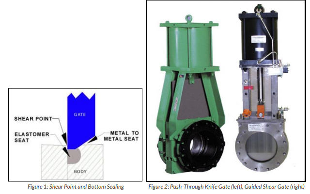
Knife Gate Valves Types (see image above):
While there are five distinct styles of knife gates, two are the primary styles used in slurry piping systems:
- Push-Through Knife Gates – designs utilize two interference fit elastomeric sleeves that are deformed by the gate when cycled. During closing, the gate is pushed through the sleeve liners and exits the bottom of the valve forcing a discharge of the process media.
- Guided Shear Gate – closed body shear gate designs utilize a guided gate with a chisel edge that is contacted by an
elastomeric or polymeric seat retained in the valve body.APPLICATION EXAMPLES IN LOW PRESSURESlurry service knife gates have been in service for over 60 years, starting on low pressure simple systems. Over the last twenty years, experience gained from the Canadian Oil Sands expanded the valve designs into more challenging and higher pressure systems, up to 10 MPa (1440-psig). Much of this design growth has been aimed at tailings applications.
Figure 3: CGIS AITF Slurry Test Loop, May 2016, Devon,
CanadaThe first 5MPa (Class 300) slurry knife gates were designed in the mid-nineties and provided to Suncor, in 1996, for their tailings lines. The oil sands tailings exhibit a greater challenge for the valve design as they are formed naturally (not ground by ball or rod mills). Thus they are far larger in particle size, are angular and have high silica content. Due to the large particle
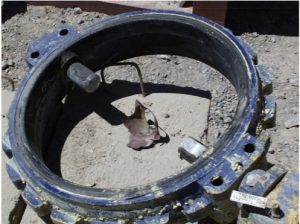
size and the higher pumping velocities (4.5 to 8 m/s) required, these tailings are considered the most abrasive in the world.Examination of valves removed from service after their operational life had been reached led tomodifications related to the basic design. The guided shear gate was now preferred based upon its ability to handle these higher pressures. The valves’ ability to provide secure containment of the process fluids, thus providing zero leakage was critical as any water based discharge would be subject to freezing for at least seven months in the northern location of the tailings plants.

Figure 4: 6-month examination of tungsten carbide weld
overlay and gate, showing no measurable wear.Wear rings were used to strengthen the abrasion and erosion resistance of the bodies and gates made from 17-4 precipitation hardened stainless steel were supplied to provide the strength and resistance needed for the slurry system. The bore of the valve was lined with chrome or tungsten carbide, applied using special overlay techniques.
It is the opinion of the authors that Push-Through knife gate valves should be limited to 2MPa and limited cycles due to the required thickness of the gate and its tendency to create a loss of seat elasticity during each cycle.
Guided Shear Gates valves have been successfully supplied for 10MPa tailings systems and are available for uni or bi-directional applications. In order to provide longer service life, single or dual wear rings (inboard and outboard) are available in a number of materials including:
- Ni-Hard (Rc 59)
- Duplex SAF2507 and AISI 4140 with chrome or tungsten carbide coating (Rc 68-72)
- Ceramic (silicon nitride and partially stabilized zirconia (Rc>72)

Figure 5: 7 MPa Australian iron tailings system – Class
600 Guided Shear GatesThe key design requirement of the Guided Shear Gate valve is to provide a shallow profile transition to reduce the effects of turbulence. The primary soft seat must be protected from the flowing slurry in order to provide zero leakage and prevent dewatering.
Guided Shear Gates valves have a design element that may cause some turbulence. When the gate is fully retracted in the open position, the area at the top of the waterway, within the chest and outside of the radius of the gate is a void.
READ PART 4: Options for High Pressure Systems
About the Authors
As the President of CGIS, Ross Waters has dedicated 35 years of his life to serving and improving the valve industry. Ross started CGIS, a valve distribution company, in 1980 in a small office in Vancouver, Canada. Thirty-five years later, the business has grown internationally and now serves clients and industries worldwide. Ross is the driving force behind increasing awareness of Severe Service Valves and is part of an MSS task forcewriting its definition. He has attended numerous conferences around the world presenting his paper, “Defining Severe Service Valves” and is well onto establishing himself as the leading expert in Severe Service. Ross is also an avid member of ASTM International G04 and has served as an expert witness.
Malcolm Harrison was born and educated in the UK and received a bachelor’s degree in mechanical engineering. After a successful career with major EPC’s working as a mechanical and piping design engineer, Malcolm relocated to the USA in 1980 to work for Bechtel in San Francisco. He eventually entered the world of valves sales in the early 1990’s. First with a specialist valve sales representative company and then as mining products industry manager with Houston-based, ValvTechnologies. In late 2014 he retired and started his own consulting company, Fluid Equipment Consulting. Malcolm now uses his vast experience to offer subject matter expert services related to all types of valve requirements.