Motivation & Objectives:
Compressors have played a key role in HVAC cooling systems since the birth of modern air conditioning in the early 20th century. Initially, toxic gases such as ammonia, methyl chloride, and sulfur dioxide, were used as refrigerants [1]. After a string of accidents caused by these noxious fluids, Thomas Midgley Jr. of General Motors synthesized the first chlorofluorocarbon (CFC) refrigerants for commercial application [2]. CFCs were utilized for most cooling systems up until the 1990s when the family of refrigerants were banned due to their connection to ozone depletion [1], [3]. R134a, also known as 1,1,1,2-tetrafluoroethane, was the first hydrofluorocarbon refrigerant introduced for HVAC air conditioning systems as an alternative to the more environmentally harmful CFC and hydrochlorofluorocarbon (HCFC) refrigerants such as R12 and R22, respectively. R134a became the dominant refrigerant because its use required little change to the devices once operating with R22, but results in dramatically lower efficiencies and high global warming potential [3].
The development of new refrigerants with favorable thermodynamic properties and minimal environmental impact is ongoing but might require a change in compressor design; as the application and regulation of refrigeration systems evolves over time, the design of such devices must follow suit. The CFturbo design software allows for such change, aiding its users to build, modify, and optimize refrigeration compressors, as shown in this case study.
Design Theory:
HVAC systems commonly utilize vapor-compression refrigeration cycles to effectively cool an environment. In this refrigeration cycle, the working fluid, or refrigerant, enters a compressor as a vapor at low temperature and pressure. The refrigerant is compressed and exits the compressor at a high temperature and pressure before passing through the condenser. The refrigerant releases heat to the surroundings as it passes through the condenser, exiting as a high-pressure liquid. Next, the liquid refrigerant passes through an expansion valve which results in a two-phase refrigerant at a lower temperature and pressure. Finally, the refrigerant passes through the cooling component of the system, the evaporator. It is here where the refrigerant gains heat from its surroundings and returns to the compressor as a vapor at low temperature and pressure. A system diagram can be seen below (Figure A). This case study isolates the compressor (impeller and volute) within the refrigeration cycle and aims to optimize efficiency while maintaining a certain pressure ratio.

Figure A: Vapor-Compression Refrigeration Cycle
Baseline Design:
A baseline design (D1) for the HVAC compressor was created using the centrifugal compressor module within CFturbo. The initial design point was defined by a mass flow rate of 2.72 pound-mass per second, a total-to-static pressure ratio of 2.80, and a rotational speed of 36000 revolutions per minute. An inlet temperature of 59 ̊F and an inlet pressure of 48.8 psi were also defined. R134a was the working fluid within the device. The meridional view is shown below in Figure B.
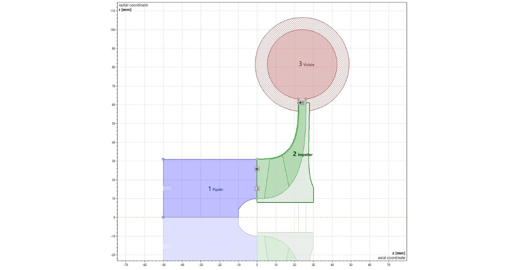
Figure B: D1 – Meridional View
CFD Setup & Mathematical Optimization:
CFturbo has full bi-directional integration with ANSYS Workbench. In this case study, the inlet pipe, impeller, volute, and outlet pipe created within the CFturbo design software was exported to ANSYS CFX. A computation mesh (Figure C) was created. Table A displays the mesh statics for the computational domain.
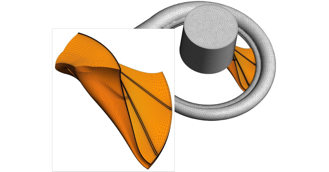
Figure C: D1 – Computational Mesh
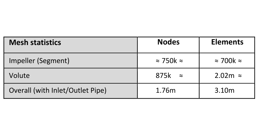
Table A: D1 – Mesh Statistics
Total pressure inlet and mass flow rate outlet boundary conditions were defined at the inlet and outlet boundaries, respectively, and a periodic boundary and rotor-stator-interface (RSI) connections were defined on the impeller blade segment. Figure D shows the boundary condition and control section setup.
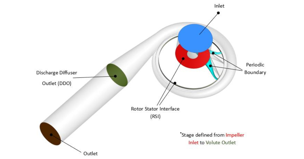
Figure D: D1 – Boundary Condition & Control Section Definition
ANSYS CFX 2020 R2 ran steady-state simulations using the k-ω SST turbulence model with a high-resolution-differencing-scheme. A Mixed-Integer Sequential Quadratic Programming (MISQP) optimization method was utilized to maximize stage efficiency while keeping the total-to-static pressure ratio in the range of 2.95 to 3.10. Eight design parameters were selected for optimization (impeller outlet width, impeller diameter, impeller blade number, impeller blade trailing edge angle, impeller blade trailing edge position, impeller-volute radial offset, volute radius, volute diffuser height) and the D1 parameter values were used for initialization. Each new design simulation took approximately 1.5 hours on a 12-core machine (AMD Ryzen Threadripper PRO 3945WX 4.00 GHz). After 141 evaluations, the solution converged with Design #107 as the optimal design proposal. Table B displays the design parameter values of D1 compared to the optimized design (D107). Figure E and Figure F compare the stage and impeller of both designs in 3D view, respectively.
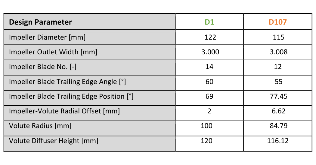
Table B: Optimization Design Parameter Values – D1 vs. D107
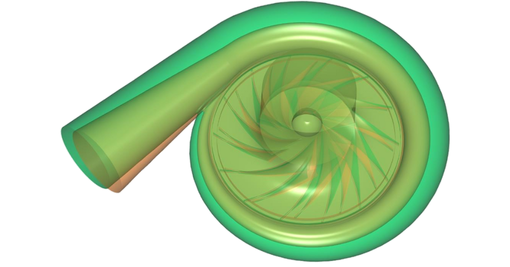
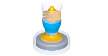
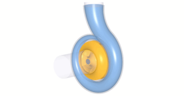
Figure E: Stage Comparison – D1 vs. D107
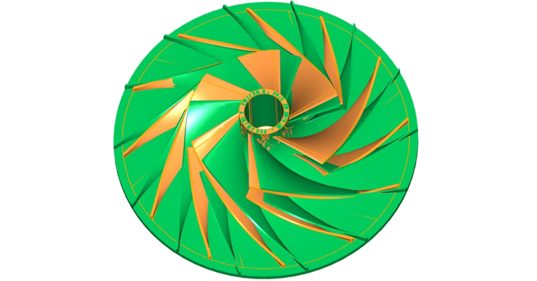
Figure F: Stage Comparison – D1 vs. D107
Results:
After optimization, a mass flow rate sweep was performed using D1 and D107. Figure G and Figure H display the stage pressure ratio and stage isentropic efficiency of both designs at various rotational speeds, respectively. The solid lines correspond to the total-to-total definitions of the relevant performance parameter, while the dotted lines correspond to the total-to-static definitions.
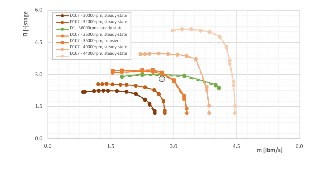
Figure G: Stage Pressure Ratio – D1 vs. D107
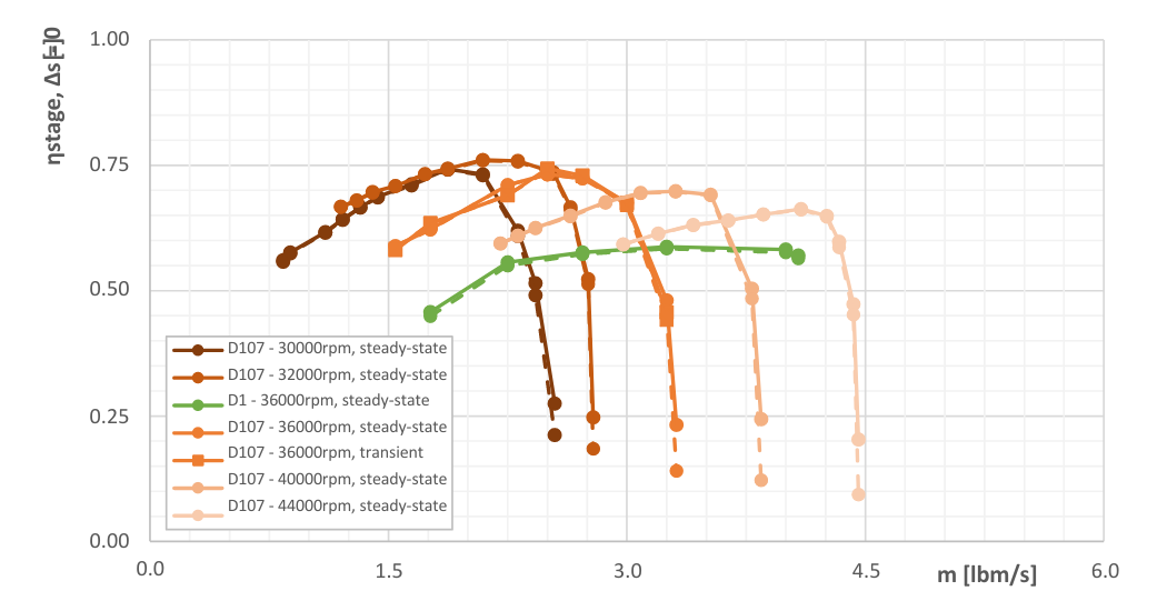
Figure H: Stage Isentropic Efficiency – D1 vs. D107
With optimization, D107 meets the performance targets. At the design point, the stage efficiency increased by 14-points after optimization while the total-to-static stage pressure ratio remained in the desire range of 2.95 to 3.00.
Conclusion:
This optimization workflow can be used on a wide range of devices to improve turbomachinery designs. CFturbo was effectively able to provide the user with a basic refrigeration compressor design and then optimize that design based on performance objectives and constraints with ANSYS Workbench. With the constant regulation faced within the HVAC industry, CFturbo can seamlessly help you redesign compressor geometries to maintain peak performance regardless of the refrigerant used.
Works Cited:
[1] J. W. Elkins, “CFCs and their substitutes in stratospheric ozone depletion.”, NOAA Earth System Research Laboratory Global Monitoring Division (GMD), NOAA Global Monitoring Laboratory, R/GML1, 325 Broadway, Boulder, CO 80305-3328. Available: https://gml.noaa.gov/hats/Halocarbons_and_ozone_depletion.pdf. [Accessed: Apr. 25, 2023].
[2] J. A. Williams, “This 1920s Inventor Sped Up Climate Change With His Chemical Creations,” History.com, 23-Aug-2019. [Online]. Available: https://www.history.com/news/cfcs-leaded-gasoline-inventions-thomas-midgley. [Accessed: 25-Apr-2023].
[3] Refrigeration handbook, SWEP North America, Duluth, GA. [Online]. Available: https://www.swepusa.com/refrigerant-handbook/refrigerant-handbook/. [Accessed: 25-Apr-2023].
About CFturbo:
CFturbo (est. 2008) is headquartered in Dresden, Germany, with a major office in New York City, New York. The company is supported by a global network of distributors and has gained worldwide respect within the Turbomachinery community over the last ten years. CFturbo is dedicated to Turbomachinery design and related engineering services in design of rotating machinery, fluid flow, and heat transfer.
Our conceptual design software is the most user-friendly system available on the market—through its unrivaled, intuitive, and user-friendly design process, CFturbo software empowers every user, regardless of experience. The software can be used to design a variety of turbomachinery-related devices, including pumps, fans, blowers, compressors, turbines, stators, and volutes. CFturbo, Inc. offers a variety of Turbomachinery engineering services including aerodynamic and hydraulic designs, CFD and FEA simulation, rotating machinery optimization, mechanical design, prototyping, and testing. For more information, visit cfturbo.com.