In this video we’ll be demonstrating a conceptual design of a mixed-flow bowl diffuser pump.
First you create a new project choosing the pump design module. Insert the design point of the pump. The design point is defined by volume flow rate, head, and rotational speed. In this case, the fluid is water. On the right side you’ll see the specific speed and the general machine type.
Now we add a new component, choosing the radial mixed-flow impeller option. In this example, we will make a semi-automated design by clicking on the green checkmark at the bottom of the window.
By clicking the green checkmark, we complete the impeller design.
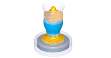
Immediately we can see a 3D model of the blades and the hub and shroud contour.
Next, you’ll get a brief overview about the design steps of the impeller. In the main dimensions window we can set options for multiple stage design, parameters to calculate the main dimensions, and estimations of efficiency.
CFturbo uses numerous empirical correlations to get reasonable initial designs. These approximation functions are taken from textbooks, research papers and own data.
The impeller main dimensions hub diameter, suction diameter, impeller diameter and outlet width can be adjusted manually if required. This will influence subsequent design steps.
On the right side of the window you see the Cordier diagram and important physical values.
In the next design step, we can adjust the meridional contour.
On the right side of the window there are diagrams for area progression, static moment and curvature which can assist you in shaping the meridional contour of the impeller.
All Bezier points can be modified numerically by changing numbers in the pop-up window.
The user can adjust axial length of the impeller, as well as shape and position of leading and trailing
Now we add hub and shroud solids. For example, we can split the curves or transform them into Bezier splines. For demonstration purposes, we’re choosing a very simple model of the hub and shroud contour. This tool is very flexible for modeling hub and shroud geometry.
The description of hub and shroud contours will be part of the secondary flow path design which will be done later.
Now we see hub and shroud model also in 3D.
Hub and shroud solids, as well as blades can be exported later into any CAD-format or meshing tool for FEA analysis.
Here we see the blade properties window. In this we define the number of blades as well as the blade shape and thickness. There are several models implemented for a slip factor correlation. For pumps, the most common is the Guelich Wiesner model. Using these parameters, blade angles on leading and trailing edges will be computed on every span.
On the right side of the window we have a graphical representation of the velocity triangles.
In the next design step, we do the meanline design which determines the curvature of the blade between leading and trailing edges on every span. The wrap angle of the blade can be adjusted graphically or numerically. On the right side of the window we have several diagrams to evaluate geometrical and physical properties. The user can choose between two different design modes for meanline design: theta over meridional contour m, or beta over m. Meanlines can be coupled or uncoupled.
Now we do the blade profiling. We ca choose between linear and freeform distributions. Different possibilities are given to define the blade thickness, as well as symmetric or asymmetric profiles. In freeform-mode CFturbo has the capability to read in profiles, for example from NACA profile catalogue, or own point-based profiles.
The last design step of the impeller is to create the shape of the leading and trailing edges on different spans. The user can choose between simple, linear, elliptic, and Bezier. Diagrams on the right side support this process.
At this point we are ready to create the second component, which is a vaned diffuser, also known as a bowl diffuser. Again, we choose the semi-automatic mode to create an initial geometry. Later there is a possibility to modify meridional contour, leading and trailing egdes, blade angles and blade profiles of the vaned stator.
Immediately we see the initial design proposal in our 3D viewer. On the left side of the window there is a model tree showing components and sub-components which allow easy navigation, renaming as well as adjusting color and translucency.
In the meridional view we can adjust the leading and trailing edge of the blades as well as the general shape of hub and shroud. To design such components, you should be an experienced user. Or, to optimize the shape and blades of the vaned stator, you can use 3D-CFD simulation and optimization techniques. State-of-the-art CFD-simulation codes like ANSYS-CFX, FINE/Turbo, StarCCM+, Simerics MP or TCFD are widely used. In addition, CFD-and FEA-simulations can be combined with optimizers to compute the best possible model geometry.
To prepare a CFD model, the gap between impeller and vaned stator should be closed. To do this, we can use the built-in capabilities of CFturbo.
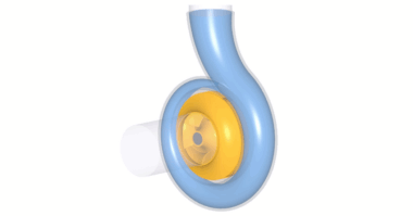
Now we see the closed flow domain in our 3D viewer. Finally, we add pipes on inlet and outlet. These pipes should have an appropriate length in order to avoid negative impact from the boundary condition to the pump stage itself.
As mentioned before, we always recommend 3D-CFD-simulations to evaluate Pump geometry models designed CFturbo.
For Turbomachinery CFD-simulation codes like ANSYS-CFX, FINE/Turbo, StarCCM+, Simerics MP or TCFD allow cost-effective, accurate predictions of performance, hydraulic efficiency, shaft power, torque, NPSH and cavitation in general.
In recent years it has become more and more affordable to combine Turbomachinery design software and CFD-codes with optimization algorithms due to lower computational cost.
However, it is essential to create robust, automated workflows which allow a user-friendly access to those sophisticated methods.
In general, it seems to become an exciting possibility for non-experts to create highly efficient pumps.
Our model is ready for geometry export. Before we export the file, we save it. CFturbo has export formats to all major CFD-codes and CAD-systems, as well as neutral formats like STEP, STL, or ParaSolid. In the next step we will open the export window.
This model is exported to SimericsMP. Simerics MP is a modern, robust, fast, accurate and cost-effective general purpose 3D-Navier-Stokes-code. CFD-simulations with Simerics MP provide realistic results that compare accurately with multiple field tests.
We have to choose settings for meshing and simulation.
We’ve chosen mesh settings which will create a mesh of about two million nodes. Mesh size can be adjusted and refined. It will become a hexahedral binary tree mesh.
In the solver settings, we have to choose between transient or steady state simulation, number of iterations or time steps and differencing scheme.
To export the model to SimericsMP, STL files are generated including boundary conditions.
The user has the option to start meshing and CFD software immediately, or just to export the files, as it is shown here.
Here we see here a screenshot of a converged solution for the steady state simulation using Simerics MP. Besides residuals we’re able to monitor physical properties and integral values like head rise, hydraulic efficiency, shaft power and torque. This steady state simulation on a two-million-nodes mesh took about thirty minutes on a laptop with an Intel I-7 processor. A transient simulation with four revolutions takes less than two hours.