In this video we’ll be demonstrating the aerodynamic design of an axial, low-pressure fan, including a CFD-simulation.
First you create a new project choosing the ventilator design module. Insert the design point of the fan. The design point is defined by volume flow rate, total pressure rise, and rotational speed. In this case, the fluid is air at 20 degrees Celsius. You can choose any fluid properties by choice, or by applying a fluids database. We can switch the rotational direction or add an inflow swirl, if required. On the right side you’ll see the specific speed and the general machine type.
Now we add a new component, selecting the “axial impeller” option. The main dimensions window opens. In this example we use an unshrouded, standard impeller. We have two general options for blade design: “Airfoil” or “Meanline” mode. Here we have chosen the “Airfoil” method.
In CFturbo there is also an option for multistage design, including contra-rotating impellers. This time we won’t use it. It will be in a separate demo video.
To calculate the impeller main dimensions, CFturbo uses numerous empirical correlations in the parameters section. In most cases, non-dimensional approximation functions are taken from textbooks, research papers and our own data. Here we use the work coefficient to calculate the impeller diameter, and a diameter ratio function to get the hub diameter. Additionally, several empirical efficiency correlations are implemented too to get reasonable initial values of the impeller main dimensions.
Now the impeller main dimensions have been computed. On the right side of the window you see important physical values, a sketch of the meridional section, the Cordier diagram and initial velocity triangle on inlet and outlet of the impeller.
In CFturbo all geometrical parameters can be adjusted manually if required. Here we modify hub diameter and impeller diameter slightly. This will only have a minor influence on subsequent design steps.
If there is a need to edit the impeller main dimensions later – for any reason – you always can go back to this design stage.
The meridional view allows the design of the meridional contours of the impeller.
On the right side of the window there are diagrams for area progression, static moment and curvature which can assist you in shaping the meridional contour of the impeller.
All Bezier points can be modified numerically by changing numbers in the pop-up window.
The user can adjust axial length of the impeller, as well as shape and position of leading and trailing edge.
Now we add hub solids. For example, we can split the curves or transform them into Bezier splines. For demonstration purposes, we’re choosing a very simple model of the hub contour. This tool is very flexible for modeling hub, and shroud geometry if applicable.
In the blade properties, at first, we set the number of blades, which is an input value with strong effects on the blade profile geometry. Then a method must be selected to calculate the radial equilibrium from hub to shroud.
The meridional and circumferential velocity components can be adjusted to balance pressure and centrifugal forces. In many cases it is useful to choose the “variable load” option that enables you to shift the blade loading from hub to shroud.
In the “Profile selection” window the user selects blade profile. It could be done from a NACA profile catalog, or by point -based data. User-defined blade profiles can be easily implemented. For this demo we have selected an NACA 6509 profile.
In the right side there are several diagrams with aerodynamic values and criteria to evaluate the profiles, for example solidity or De-Haller criteria.
If required, the profile properties like stagger angle or chord length can be adjusted manually.
In the next window there is the actual status of the blade profiles, showing more detailed information of the current design. For example, we can evaluate blade thickness, blade angles on leading and on trailing edge, blade passage area, a blade-to blade view, and so on.
For NACA profiles there is a possibility to set a finite thickness on the trailing edge of the blade.
Blade sweeping is a possibility to deform the blade profiles in meridional and in circumferential position. It is mainly done to get better acoustics. Axial fans can become quieter this way. The empirical, so-called acoustic benefit is shown on the upper right side of the window. However usually this goes along with some losses in efficiency and performance. It is a trade-off.
Now we can see the impeller in its actual state in our 3D-viewer. On the left side of the window, you have the model tree with all components and subcomponents.
This allows for easy navigation, renaming, and graphical adjustment.
The user can modify color and translucency for each component, or subcomponent.
To prepare the CFD set-up first we add an inlet extension, including a simplified hub nose. For this purpose, we apply the “Stator” module of CFturbo which can be used to make vaned and un-vaned Turbomachinery components like pipes, or guide vanes.
The inlet pipe should have a certain length in order to prevent an impact from the boundary conditions to the fan stage itself when running a flow simulation.
In our example we want to create a simplified hub nose which will be placed directly upstream of the impeller. We split the hub curve, change the curve type to “Bezier” and create a rounded shape of the hub nose.
Every single Bezier point can be numerically defined as shown for the Bezier point on the z-axis.
As done before for the impeller we have added a solid shape for the material domain of the hub nose, an additionally for the outer diameter.
Now the model will be shown in the 3D-viewer again.
Both components can be showed or hidden.
Solids models of the whole impeller including blades and blade fillets, or of the stator components can be exported into any CAD format or meshing tool for CFD/CHT/FEA analysis. Direct export to rapid prototyping via STL is possible too.
In the same way as on the inlet side, we should add a pipe or a diffuser downstream of the impeller. Here we add an axial stator.
Again, the stator should have an appropriate length. A recommendation for an outlet pipe length should be 5 times pipe diameter, or more. As before hub and shroud solid will be generated.
Our model here uses the inlet pipe and the outlet pipe just for numerical reasons to run the 3D-CFD simulations correctly.
Of course, a user can create more complex geometries like guide vanes or bends, upstream or downstream of the fan impeller.
Even a virtual test rig could be prepared to compare 3D-CFD-data and experimental results later.
Just like in the previous design steps, the model can be shown and updated in our 3D viewer. The final design step would be “Model finishing” in CFturbo, include fillet design.
Model finishing means a geometrical operation to create solid models for the fluid domain and for the material domain in excellent quality.
This fishing is a pre-condition for many geometry export-formats. It will be used often, but not for all CAD or CFD-systems. For some of the export formats the model finishing will be done automatically.
Let’s save the model before we export the geometry and prepare the simulation. We open the export window. CFturbo has export formats to all major CFD codes and CAD systems, as well as neutral formats like STEP, STL, or ParaSolid.
This fan model will be exported to SimericsMP. We have to choose settings for meshing and simulation.
For this demo we intentionally generate a very coarse mesh. We’ve chosen mesh settings which will create a mesh of about five-hundred thousand nodes only. It will become a hexahedral binary tree mesh. For single stage Turbomachinery CFD simulations we recommend 2 to 10 million nodes, depending on the number of blades and complexity of the secondary flow path.
In the solver settings, we must define the number of iterations or timesteps, and we have to choose between steady state or transient simulation and select a differencing scheme.
To export the model to SimericsMP, STL files are generated. Then the computational model will be exported, including boundary conditions.
The user has the option to just to export mesh and solver settings. Or, as it is shown here, he starts the meshing process and the CFD software directly.
By choosing this option, SimericsMP will be launched, and the meshing process will be done.
Simerics MP is an affordable, fast and robust, general purpose 3D-Navier-Stokes-solver. CFD-simulations with Simerics MP provide realistic results that compare accurately with multiple field tests on various types of rotating machinery like pumps, blowers, compressors and turbines.
Now the model is ready for simulation. All boundary conditions are set for the design point. The project file will be saved before the simulation starts.
Besides residuals, we can observe the flow field in real time. We can start dynamic streamlines or particles, show iso-surfaces, or important physical values of the flow field on all surfaces, or on sections.
Compared to others the SimericsMP CFD-solver is extremely fast. Steady state and transient flow simulations can be easily run on a laptop. This steady state simulation took just three minutes on a laptop with an Intel I-7 processor.
A fully transient simulation simulating four revolutions would take less than twenty minutes for an operating point on that coarse mesh.
For models with larger mesh sizes, such as for multistage machines, there are options for distributed parallel computing available to fulfil higher computational requirements.
Additionally, we’re able to monitor physical properties and integral values like total pressure of impeller or stage, hydraulic efficiency of impeller or stage, shaft power, and torque.
All results can be exported to Excel or other formats for further post-processing
In addition to starting the simulation manually as it is shown here, batch-mode runs can be prepared to run performance curves or maps.
We see here a converged solution for the steady state simulation. We always recommend doing transient flow simulation to get a higher level of accuracy in your predictions.
We always recommend 3D-CFD-simulations to evaluate Turbomachinery components designed in CFturbo.
In recent years it has become more and more affordable to combine Turbomachinery design software and CFD-codes with optimization algorithms due to lower computational cost.
In case design adjustments are necessary, after evaluating the simulation results, you can go back to CFturbo and modify the fan interactively.
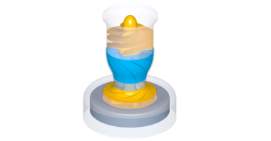
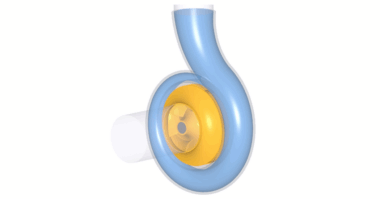
Here’s a 3D printed, prototype of the impeller we just created! It was exported directly to a 3D printer from CFturbo. There’s no need to use an external CAD system. This high-quality impeller prototype made of Nylon is fully functional. It’s ready for testing!
As you’ve seen, CFturbo is a user-friendly, straightforward solution for axial fan design, and 3D-CFD- simulation. To register for a free trial, and to learn more about our engineering services visit cfturbo.com