In this video, we’ll show an aerodynamic centrifugal compressor design. The application is a so-called “High-Speed Turbo Blower” as used for wastewater aeration.
First, we create a new project choosing the Compressor design module.
In the “Global setup” window, We specify the design point of the compressor. CFturbo aims to reach the best efficiency point (BEP) for the design point. The design point, or duty point, is defined by mass flow rate, total pressure difference or total pressure ratio, and the rotational speed. In this case, the fluid is Air at 20 degrees Celsius.
Besides the ideal gas model, different real gas models are available, like Peng-Robinson or Redlich- Kwong. The integral part of the CFturbo software is the CoolProp-database containing fluid properties of numerous gases, liquids, and mixtures.
Additional to the duty point, the inlet boundary conditions – inlet pressure and inlet temperature – must be defined. You’ll see the specific speed and the general machine type on the right side of the window.
Next, we add a new component, choosing the radial mixed-flow impeller option. In this example, we will make an unshrouded, single-stage radial compressor.
In the setup window for the main impeller dimensions, we have to set the tip clearance between the blade tip and casing. And, we must decide if we want to use “splitter blades.”
In the parameter section, we can select empirical function to design reasonable impeller main dimensions from the very beginning. In this example, we use correlations for work coefficient, diameter ratio, and meridional deceleration. An estimate for the efficiency is required as well.
The empirical correlations in CFturbo are taken from textbooks and research papers or are based on our data. Most of them are accessible and adjustable by the user. This gives a unique possibility to customize the code for own applications and to maintain proprietary information.
Our software will provide a proposal for the main dimensions such as shaft diameter, suction diameter, impeller diameter, and outlet width. On the right side of the window, we can see the essential physical values, an initial sketch of the meridional view, the impeller within the Cordier diagram, and an initial set of velocity triangles.
The user can modify all geometrical values manually. It is an available option throughout every design step of CFturbo.
In the meridional contour design window, modifications of hub and shroud contours can be made as well as shaping repositioning of the leading and trailing edges.
On the right side of the window, there is a 3D-CAD preview and an area progression diagram of the meridional flow channel. Other options to support a user shaping the impeller’s meridional contour are “static moment” and “curvature,” among others.
As shown here, we adjust the leading edges of the primary blade and splitter blade. The blade edge projections can be straight lines or Bezier splines. There is high flexibility to modify the shape of the hub and shroud by moving Bezier-points interactively. And, we can set the impeller’s axial length. All Bezier points can be modified numerically by changing numbers in the pop-up window.
After modifying the hub and shroud separately, each geometrical modification is shown directly in the diagrams. An additional design method is available in CFturbo, where you can manipulate the middle section of the meridional contour instead of hub and shroud.
Now we create the hub solids. For example, we can split the curves or transform them into Bezier splines. Bezier points can be added or removed without limitations. For demonstration purposes, here we’re creating a simple model of the hub contour. This tool is very flexible for modeling solid parts of geometry. The description of hub and shroud contours can be part of the secondary flow path design, if applicable.
Later, hub solids and blades can be exported directly into any CAD-system or meshing tool for structural or thermal analysis.
The next impeller design step is about blade properties. It mainly comprises the calculation of blade angles at leading and trailing edges of main blades and splitter blades. Several options for slip factor correlations are supporting this design step.
At first, we set the number of blades and the number of spans. Then, we choose a blade type for our application. In most cases, this selection is determined by the manufacturing method of the impeller. Then we initially define blade thickness on leading and on trailing edges. With this and a slip factor
correlation, we can calculate the blade angle on every span.
On the right side of the window, we see from left to right: velocity triangles, two tables with all velocity components and blade angle values at leading and trailing edges, a meridional sketch, and a diagram that explains the slip factor calculation.
For the blade “Meanline design”, CFturbo offers various possibilities to create the fundamental blade shape. It is mainly all about calculating the blade curvature on every span between leading and trailing edges. Since this example should be designed with ruled surfaces, with are preferred for flank milling, we only have to work with two spans: hub and shroud. For the ruled surface, there will be a linear interpolation between hub and shroud.
The blade angles of leading and trailing edges are fixed in this design step. There are graphical and numerical possibilities to modify the wrap angle of the blade, which has a strong influence on the blade angle distribution. Likewise, there are graphic and numerical options to adjust the curvature of different spans. The Bezier-curves can be modified by drag-and-drop or by writing numbers in checkboxes of Bezier points.
On the right side of the window, there are options to configure various diagrams and geometrical views to evaluate the blade design. Blade to blade calculations and blade surface calculations are based on the Stanitz-Prian methodology. Among others, we can select estimates of Mach number, absolute and relative velocities, pressure, swirl, and blade loading. A real-time, 3D-view of the blade directly shows the modifications in three-dimensional CAD.
In general, the user can choose between direct beta-distribution, m-theta-conformal mapping, or inverse design by blade loading for centrifugal compressors.
The next design step, “Blade profile design,” is mainly defining the blade thickness distribution. There is high flexibility in CFturbo to do this. The user has options for linear of freeform shapes. The suction side and the pressure side of the blades can be made symmetric or non-symmetric. You can work with different profiles on every span if necessary.
For high-performance or high-efficiency requirements, a user can import predefined profiles, like NACA, or his own point-based data.
On the right side of the window, the user has options to see blade to blade calculations or blade surface calculations as in the previous design step. The 3D-view of the blade profile directly shows the model in three-dimensional CAD.
“Blade edges design” is for the modeling and adjustment of the leading and trailing edges. There are four general types of blade edges: Simple, Ellipse, Bezier, and Linear.
On the right side of the window, the user can configure the same view options as in the previous design step. Area, progression, Mach number, relative and absolute velocities, swirl, blade loading etc., are available. The 3D-modeling of the blade edges can be seen in real-time modifications.
In this example, we have used an elliptic shape with an axis ratio of three for the leading-edge design, which is typical for those types of blades. If we would set the axis ratio to one, the leading edge becomes an arc, as shown here.
For the trailing edge, we use the simple option. The user has the possibility to trim the blade on the outer diameter of the impeller. But for the trailing edges, too, you can use curved shapes like elliptic or Bezier.
Now the basic design of the impeller has been finished. We can see a section of the model in the main Meridian window of CFturbo.
We also can show the impeller geometry in our 3D-viewer. After selecting the impeller in the model tree on the window’s left side, we can vary color and transparency. If required, any geometrical element or sub-element can be shown or hidden.
The second component we want to design in our compressor stage will be an unvaned radial diffuser. A diffuser decelerates the flow velocity to lower fluid-dynamic losses in subsequent parts, like volutes, bends, or pipes. For demonstration purposes, here, we design a simple radial diffuser of a specific radial extension. We select the general shape “Radial diffuser,” and we adjust the geometrical value numerically. On the right side, we see a sketch of the diffuser section. Additionally, there is a tab “Values” where the user can find all essential fluid dynamic and thermodynamic numbers at the inlet and the diffuser’s outlet.
Now the model is shown in the 3D viewer.
CFturbo’s volute modeling is fully parametric and versatile.
In the first volute design step, we specify the inlet data for the volute. Fluid dynamic and thermodynamic numbers will be transferred automatically from the upstream component, as shown on the right side.
Like in every other design step, the inlet geometry settings can be adjusted manually by the user.
In the next volute design step, we select the cross-section shapes. There are different options to shape the volute. From rectangular, over round, line segments to Bezier and radius based profiles are possible, symmetric and asymmetric. And, cross-section shapes may vary in the circumferential direction.
Here we have choosen a round-asymmetric model with a strictly external shape.
The heart of the volute design module is the “Spiral area” calculation. It is based on Pfleiderer or Stepannoff’s theory. A user can select the constant swirl or constant circumferential velocity approach. Alternatively, CFturbo offers the capability to set an area progression, defined by the user. Together with our cross-section area options, this allows high flexibility in volute design.
On the right side, you can select and configure diagrams and view options to support the design process visually. At any time, the 3D-viewer of the full model can be used to check the geometry. The next volute component will be the discharge diffuser.
The discharge diffuser is usually necessary to connect the volute itself with a piping system. It is a critical component, both for aerodynamic and aero-acoustic reasons. The volute and its discharge diffuser have to fit perfectly into the impeller.
We can modify the length, the outlet diameter of the diffuser, and its outlet cross-section. The initial created tangential diffuser can be made with n centric or with non-centric outlets. Besides tangential outlet directions, there are options to make radial, or spline-based shaped discharge diffusers. Another kind of flexibility is given by a z-bend option.
The Cutwater or Tongue connects the spiral casing to the discharge diffuser. The tongue’s right design is challenging, too, because of aerodynamic, aero-acoustic and structural requirements, and manufacturing constraints.
For the tongue design, there are currently three design options in CFturbo: Simple, Fillet, and Sharp. Here we create a Fillet replacing the initial simple cutwater design.
We can modify the radius and the spiral start position. Here we specify a 1mm radius. The shape of the
cutwater will be automatically updated in our 3D viewer on the lower right side. Above, we see a table
with essential geometrical data describing the tongue.
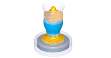
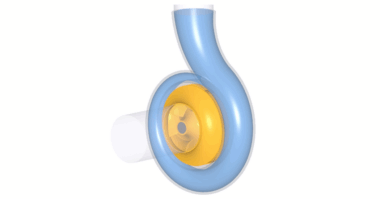
Next, we see the full model with impeller, radial diffuser, and volute in the 3D viewer of CFturbo.
Now we take steps to prepare the CFD model. At first, we add an outlet extension downstream of the discharge diffuser. For numerical reasons, the pipe should have an appropriate length to prevent an impact from the boundary conditions to the compressor stage itself. Here we have added a 300 mm outlet pipe about three times the diffuser outlet diameter.
Second, we have to close the gap between the impeller’s outer diameter and the radial diffuser’s inlet. To do this, we go to the CFD-setup menu of the impeller. We have to mark the RSI outlet checkbox on the right side. RSI stands for Rotor-Statot-Interface connection.
As an alternative to the CFD-setup’s RSI connection, a user could define explicitly place a small stator between impeller and radial diffuser.
To finalize our compressor stage and prepare the CFD-simulation model, we add a pipe on the impeller’s suction side. Likewise, for numerical reasons, the inlet pipe should have an appropriate length to minimize the inlet boundary’s impact on the compressor impeller. In this specific case, we add an inlet extension of 100 mm. We have two options: on the one hand, we could create a pipe with a simplified shaft model, as shown. To do this, we specify the inlet and the outlet position of the pipe, or just the length. There are several models to create a vaned stator quickly. The user can choose between freeform, axial, radial, and 90 degree bends. On the right side of the window, we see a simplified sketch of the stators’ meridional contour. The impeller and shaft geometry is shown in the 3D viewer as well.
In most cases, these single-stage centrifugal compressors have bearings on the motor side only. There will be a hub nose at the impeller’s eye, or the end of the shaft is left blunt.
For the actual model, as shown, we design a hub nose. At first, we have to modify the main dimension of the inlet. Then, we split the lower curve into two sections. One part is representing the axis, and the second part will describe the hub nose contour.
The hub nose can become a simple circular area, a cone, or it can get a freeform contour made of one or more Bezier-splines. A combination of Bezier splines and straight lines would be possible too. In this model, we use the latter. In CFturbo, the modeling of rotational curves and surfaces is versatile and flexible. The exact positions of each Bezier point can be set or modified numerically.
We check the geometry in the 3D-viewer of CFturbo, and we change the color of the hub nose. The user should be aware of specifying this part as a rotating wall in his CFD-setup. Adding inflow components upstream and outflow components downstream of the compressor stage completes the computational domain already in CFturbo. Such a possibility is helpful, especially to setup for automated design space exploration and optimization.
In CFturbo, there is the option to rename the components at every time. Renaming is not mandatory, but it can be useful for organizing and structuring the model better. Here, we rename all parts, now called PipeIn, Impeller, Diffuser, and Volute, in the flow direction. The Volute outlet extension can be exported as a separate part if required.
Dependent on the interface, the given domain names will be adequately exported to CAD, CFD, and FEA software. Codes may have different requirements on name conventions.
It is essential if the user intends to make automated design space explorations or setup optimization workflows.
Before we proceed, we save the CFturbo file.
Before exporting the model, it is recommended to make a “Model finishing” in CFturbo. Model finishing
is an operation to create high-quality solid models of selected components. Model finishing is required for some export interfaces, but not for all.
And, in this design step, there is an option to specify fillets between blade and hub. In our example, we set a 0.5 mm fillet radius with connects the impeller hub with the main blades and the splitter blades.
Considering the fillets is essential, especially for structural modeling. But also for flow analysis, if the dimension of the impeller is small compared to the fillets.
As shown, CFturbo has export options to all significant CFD-codes and CAD-systems and neutral formats like Step, STL, or Parasolid.
Interface development is a crucial part of the CFturbo development strategy. It is the basis for parametric design exploration and automated optimization.
This example is exported to CFturboMP, also know as Simerics MP. Simerics MP is a modern, robust, fast, accurate, and cost-effective general-purpose 3D-Navier-Stokes-solver.
Correctly done, 3D-CFD-simulations can provide realistic predictions that compare accurately with experimental investigations.
We see here a converged solution for the steady-state simulation. It took less than one hour on a notebook with an i9-processor to solve this compressible flow case using a 2 million nodes mesh. In general, we recommend doing transient flow simulation to get the best level of accuracy for performance predictions.
As mentioned before, interface development is an essential part of our development strategy. It is the basis for parametric design space exploration. In case geometry adjustments are necessary, you either go back to CFturbo and modify the geometry interactively. Or, you can set up an automated workflow using CFturbo’s batch-mode capabilities.
This slide shows the principle of an automated optimization workflow. CFturbo can be easily combined with any CFD- or FEA-code and optimization software. For example, there are setups available for Ansys, Fine\Turbo, Star CCM+, or Simerics together with optimization codes like optiSlang or HEEDS, among others.
Through its bi-directional integration of CFturbo into Ansys Workbench, there is a truly seamless, highly productive way to work with CFturbo and Ansys products like TurboGrid, CFX, or Ansys Mechanical. It offers interactive or automated design optimization.
To download a free trial and learn more about our software and engineering services, visit cfturbo.com.