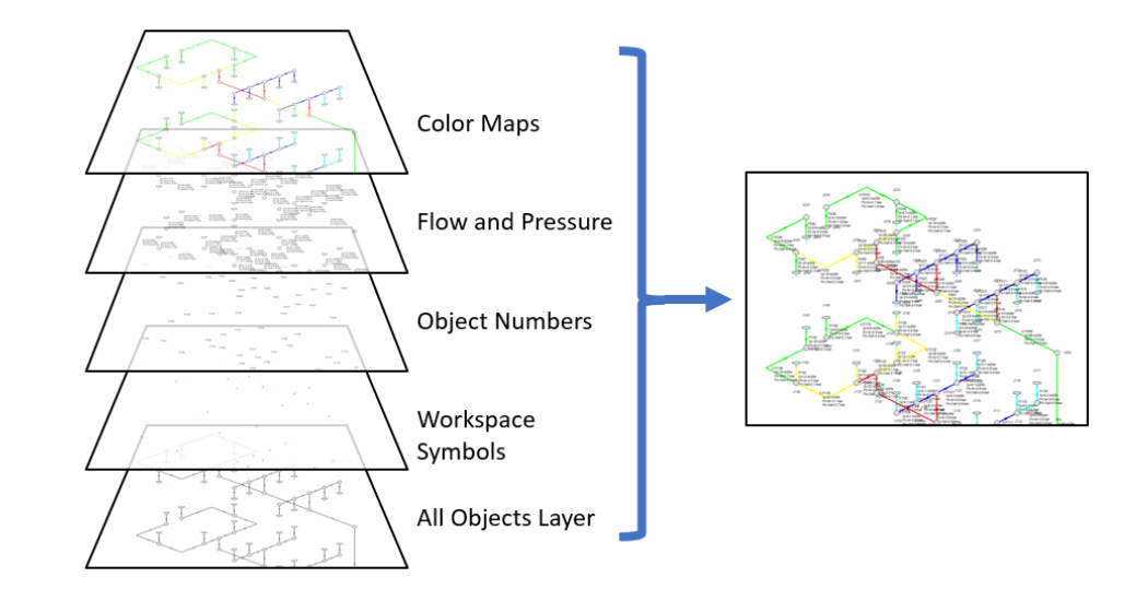
Applied Flow Technology is excited to share Workspace Layers, a new feature for the Applied Flow Technology software suite that you’ll be working with soon! A group of layers is like a stack of transparencies. Each layer displays specific, customizable information and together they combine to form the Workspace view for your model.
This is concept is much like Adobe Photoshop. Layers determine the visibility of the objects in the Workspace, but all objects exist regardless of visibility for connectivity and calculation purposes. Creating, customizing, and toggling Workspace Layers gives you more control over viewing your data than ever before.
Basics and UI
Layers can be shown or hidden to create different views of the workspace. The visibility of objects in the workspace depends on the layers that are shown, as objects on hidden layers are not shown on the workspace unless present on another layer. If an object exists on multiple layers, only the top-most representation is visible – which object is considered to be the top-most representation is determined by the layer order. For example, if a tank is colored pink in the top layer, and the standard aqua in the bottom layer, and both layers are shown, you will see a pink tank on the Workspace. If the top layer is hidden, the tank will appear aqua.
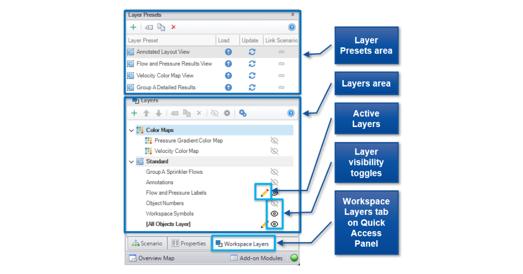 The Workspace Layer tab on the Quick Access Panel (QAP) is a new tab on the QAP along with the existing Scenario Manager and context-dependent Properties view. This panel consists of two main areas – Layer Presets and Layers. Layer Presets allow you to quickly preserve and revert to a set of shown/hidden layers. The Layers area breaks down layers into categories of Color Maps layers and Standard layers.
The “primary” layer is the All Objects Layer, which is a special layer where all objects are visible that are present in the current scenario. This provides both a simple way to view all objects and serves as the baseline on which the other layers build. While the All Objects Layer is always the bottom-most layer, the other Standard layers can be reordered up and down the layer stack with the arrows at the top of the Layers area, which is also where you can duplicate, delete, and rename layers, and where you can change Global Layer Settings. Next to the name of each layer, which are ordered from the top-most to the All Objects Layer, you can toggle the visibility setting of that layer.
By default, new objects are visible only on the All Objects Layer. However, if layers are set as Active Layers, then any new objects that are created and their labels will be visible within all Active Layers. Active Layers are set by hovering over a layer and clicking the pencil icon and any currently Active Layers are denoted by the pencil icon.
As mentioned before, Layer Presets allow the status of the layers, i.e. whether they are shown or hidden, to be retained. There are four columns in the Layer Preset area. One shows the name of the preset, the Load Preset option allows it to be loaded into the Workspace, the Update Preset option saves the current layer states to that Layer Preset, and the Link Preset option links that preset to the currently active scenario.
By linking the preset, it will automatically load whenever that scenario is loaded in the future. Individual layers, by contrast, are not tied to a specific scenario and are defined globally and immediately available in all scenarios. A layer can only show objects that exist in the active scenario, and changes to the style of an object in a layer will affect all scenarios.
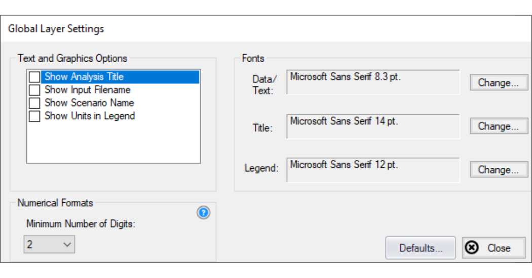
Some settings, such as font style, affect all layers and are controlled in the Global Layer Settings window.
 Editing Layers
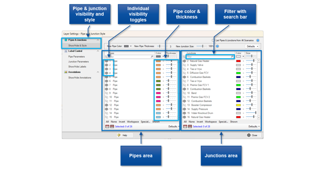
The Layer Settings window has a similar look and feel to the Analysis Setup window, with a menu of navigation panels laid out on the left. The Pipes & Junctions area of the Layer Settings window allows the pipe and junction style to be defined for a given layer, along with which pipes and junctions are visible. Note that changes to this panel are made live, no Apply button is needed to apply the changes that you make.
Some object properties have been moved to the Layer Settings. Pipe color, style, and display text are now set as part of a layer, not in the Pipe Property window. These are in the Show/Hide & Style panel. The name, number, visibility, color, and size/thickness are listed for each pipe and junction in the model. Junction icons are not edited in the Layer Settings, these are still edited in the Workspace or with global junction edit.
The usual selection options, including Select Special and Workspace options are present for selecting which objects to mass edit via the color and size options at the top of the table and each object can also be individually edited within its row. There is a toggle to show pipes and junctions that are not present in the current scenario, but these are hidden by default. Layers apply globally to all scenarios, so this option is available to reduce the potential for unintended changes to other scenarios.
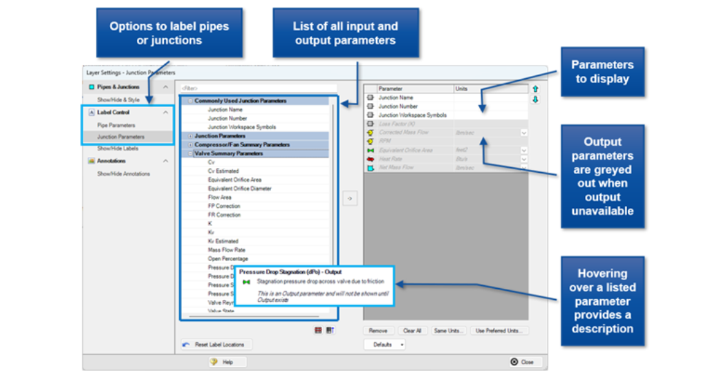
 Label Control
A Label refers to any text associated with an object – for example, pipe numbers, names, flow rates, and so forth. The Label will display a unique combination of defined display text items from each visible layer. Input and output information is displayed together; there is no separate “input” or “output” mode. Inputs in labels are always visible, while outputs are only displayed when there is output available for the active scenario. Labels can be hidden from individual objects within a layer and are hidden when toggling off the visibility of their associated layer. Label text order is now a combination of layer order and parameter order within each layer.
 Color Maps
Color Maps and animated color maps return as a type of special layer! There can only be one special layer displayed at a time and they override the behavior of standard layers in the model. Unsurprisingly, Color Maps supersede any colors you have assigned to pipes when they’re active. While only one Color Map can be active at a time, the Workspace Layers system improves on the previous Visual Report system by allowing you to switch between active Color Maps quickly without losing your customizations to colors, thresholds, and units!
Improvements from Visual Report
Do you love Visual Reports and are afraid of change? There’s no need to be, Workspace Layers offers all the functionality of the previous Visual Reports system with several key improvements and more power and flexibility. There is no distinction between input and output data, you can now show both simultaneously on separate layers and even the same layer. Workspace Layers improves your workflow by eliminating the need to switch back and forth between the Workspace and Visual Report when you want to change some element of your model. There is also no need to enable a parameter and assign the desired unit in Output Control before you can use it as a label in Workspace Layers. Again, this can now be done without leaving the Workspace. It’s possible to complete an entire project from start to finish without ever leaving the Workspace.
You can now display different parameters for different pipes or different junctions of the same type by putting the parameters in different layers. This empowers you to present your results in a cleaner, more focused manner – all the outputs you want and nothing you don’t. Annotations have also been overhauled as part of the transition to Workspace Layers – more on this soon!
Want to go hands-on with Workspace Layers? Keep an eye out for this new software versions this summer!