Classically, hydraulic loss tends to be categorized as major losses, which are due to friction between the fluid and the pipe’s inner surface, and minor losses, which are due to entrances, exits, fittings, and other component effects. Losses due to friction tend to have a greater impact on the hydraulic resistance and this could be the main reason that we classify it as the major of the two losses. However, to be professionals at our craft, we ought to get a full vision of both losses and apply them properly, namely when they affect the reservoir junction.
A user must be intentional to neglect major loss within an AFT Fathom model. The moment the pipe properties menu is open, the required information includes the pipe diameter, length, and absolute roughness. These three values determine an fL/D term for frictional loss; the model won’t run without these defined when the absolute roughness frictional model is selected.
Entrance and exit minor loss within the reservoir junction, on the other hand, is a bit easier to overlook. After all, it’s not on the main tab, but the second tab that’s named “Pipe Depth & Loss Coefficients”. Navigating to this tab, the connected pipes, an optional connection type, and K-Flow into/out of pipe are available for definition. At AFT, our design philosophy is not to assume anything about a user’s inputs but instead to let the user explicitly define their model. This is apparent as the default K-Flow out of pipe is set to 0, lossless.
There are a lot of published values for Representative Resistance Coefficients, also known as Loss Coefficients, popularly denoted as K or lower case xi. Referring to a popular resource, Crane’s Technical Paper 410, pipe exits of various kinds should be set to K = 1 [1]. A Loss Coefficient of 1 simply represents a complete loss of all kinetic energy between the exit of the piping system and coming to rest within an infinite reservoir. Interestingly, this applies whether the flow is discharged below or above the surface. The flow being discharged below the surface dissipates this kinetic energy by pushing itself into the inertial reservoir. The flow being discharged above the reservoir will be resisted by the atmospheric pressure from the air and fall into the reservoir where it at some infinite point away, comes to rest, i.e. losing all its kinetic energy (K=1.0).
“Are there cases where the exit Loss Coefficient is not equal to 1?”. Now you’re thinking! The Loss Coefficient may not equal (though still be close to) 1.0 when one of these conditions is met:
- Diffusers, elbows, or other obstructions exist at the discharge, producing greater hydraulic loss.
- Fluid within the discharge body is moving, i.e. a river or mixing vat, decreasing the resistance for the fluid to enter the reservoir.
- Flow is compressible, complicating everything.
This isn’t a comprehensive list but a general way to think about it is whether the reservoir inhibits or enables the flow to exit the pipe compared to the reservoir at rest with a pipe that has no obstructions.
“Well, that’s all fine and dandy, but it’s a minor loss. It will be fine if I don’t account for it”. Perhaps. Let’s explore how much difference excluding the loss can impact your results.
Example AFT Fathom Model that Excludes Minor Loss
For the sake of this example, we will say a 5% or greater difference between the calculated velocity using or excluding entrance/exit losses would warrant the need to define these minor losses (I’m not endorsing that 5% is a “good” number for systems. Only to illustrate my point. You should determine your own margin of confidence). Using the simplest model you can build in Fathom, two reservoirs connected by a single pipe, we will have version A defined as no loss entering or exiting reservoirs and version B will be defined with a sharp-edged entrance (K = 0.5) and exit (K = 1.0), summed to K = 1.5.
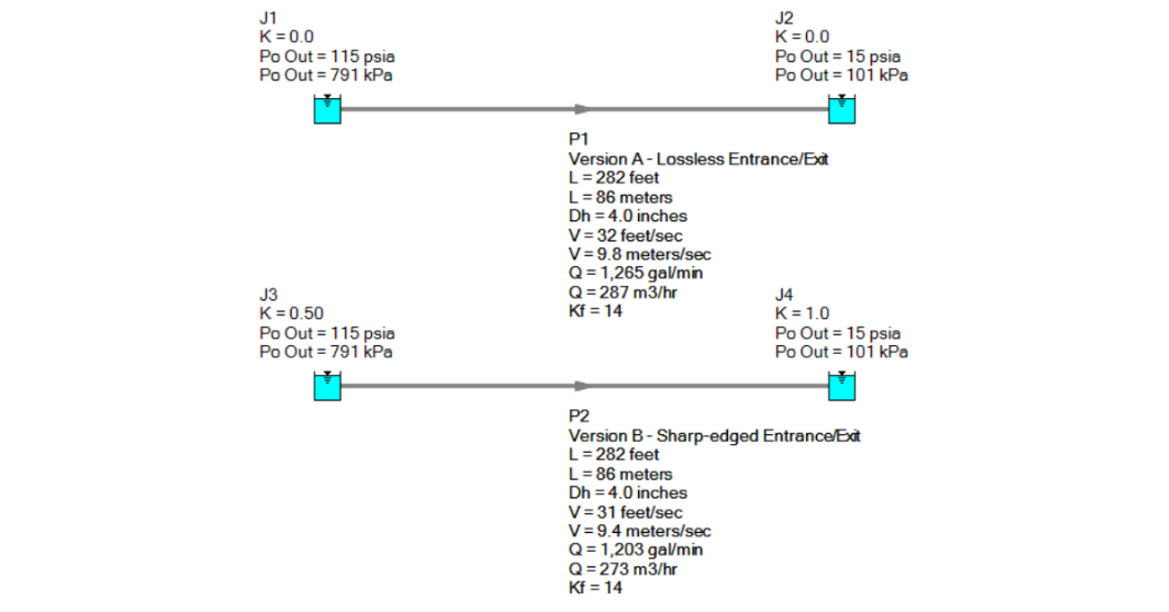
Figure 1. Version A and B were modeled within AFT Fathom.
In our pressure loss equation including both K and fL/D terms, we can calculate a length for a given diameter which results in a 5% difference in flow velocity between versions A and B shown above. We are using steel pipe and water for these calculations as a control. Taking a range of popular pipe diameters, we produce Figure 2, determining the length where the velocities differ by 5% when including or excluding minor loss.
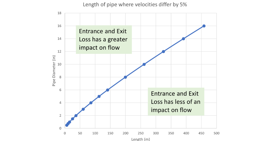
Figure 2. Pipe Diameter (in) vs Length (m) where the velocities differ by 5% when comparing lossless with sharp-edged entrance/exit.
Looking at a 4″ pipe, the size of a balled-up fist, a pipe roughly longer than a football field (American or International are “almost” the same length, go figure), will be less impacted by the minor loss than the frictional loss in the pipe. The reverse is that if the pipe is shorter than the football field, those minor losses may become significant quickly. The same goes for larger pipe diameters.
Focusing on the 4″ pipe and varying the length from 0.1 to 1000 meters, we can make a new graph to display the percentage difference between the two velocities. This shows how quickly the percentage difference increases as the pipe length decreases.
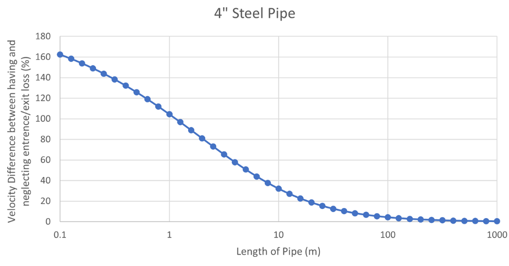
Figure 3. Velocity difference (%) vs Length (m) for a Steel 4” Pipe transporting water.
So, you may be left wondering “When should entrance and exit losses be applied? Only if I’m working with a short pipe? And how short of a pipe for all situations?” My advice to you is simple: simply add them all the time if possible. It’s quick and easy. It can only help, not hinder your pipe hydraulic calculations. However, at a minimum, a classy engineer ought to know when excluding them will have a significant impact on the results.
For even more considerations surrounding minor losses, look forward to next week’s webinar, “When Minor Losses aren’t so Minor” where we will ‘mine out’ all the kinds of minor loss details.
[1] Crane Co., Flow of Fluids Through Valves, Fittings, and Pipe, Technical Paper No. 410, Crane Co., Joliet, IL, 1988.