Water utilities for heating and cooling are critical to the safe and effective operation of many power plant systems. These utilities are also valuable for heating a plant’s surrounding infrastructure, providing HVAC heating to buildings from a plant’s existing heating infrastructure. The design of these infrastructure systems is subject to a range of operating conditions, such as variable seasonal heat demand, or changing demand from day to night for continuously operating power plants. These systems must also consider start-up and emergency conditions, requiring a robust system capable of a wide range of operating points.
Agnieszka Markwica with Energoprojekt Katowice was tasked with modeling the hot water network of a power plant in AFT Fathom, capturing heat to deliver to the surrounding buildings’ HVAC via heating water. Markwica was to consider the system’s heat transfer requirements, as well as alternatives when heat requirements shifted or consumers were temporarily closed off.
Building the model
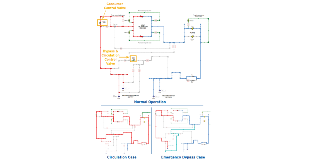
Markwica began by making a precise model of the system infrastructure, relying on technical documentation for fittings and instruments and system data for piping dimensions. Complex components like heat exchangers were modeled as resistance curves, capturing pressure loss data across a range of flowrates. Heat exchanger temperature considerations were similarly modeled via the Controlled Downstream Temperature model. Markwica also color-coded the model, indicating colder feed water in blue and hot delivery water in red. Color coding made the model immediately readable to other engineers and the client. Figure 1 shows a Workspace diagram of normal operation, highlighting the control valve elements used for the alternative emergency and circulation operating cases below.
With an established model, Markwica sized the system’s pump according to the design required flow and corresponding pressure requirement. This single pump would provide the HVAC system’s wide range of required flows, anywhere from 20 m-tons/hr (22 tons/hr) at minimum circulation flow, 67-174 m-tons/hr (74-192 tons/hr) in emergency cases, and up to 241 m-tons/hr (265 tons/hr) at normal operation. The flowpaths for these alternative cases are shown in Figure 1.
Sizing Equipment
The wide range of operating flowrates was addressed with control valves and a variable frequency drive (VFD) to change the speed of the pump. Adjusting pump speed provides more flexibility to meet an intended operating point efficiently rather than relying on control valves to create additional losses. A pair of control valves controlled the flow distribution between the heat exchangers and a bypass depending on the operating case. Due to the wide range of flowrates to control, Markwica tested multiple components across a range of diameters, relying on AFT Fathom to indicate the corresponding Cv and Open Percentage for each operating point. Properly sizing these control valves in conjunction with variable pump speed ensured Markwica selected the most optimal variant in each case.
Alternate Operating Cases
Markwica faced other considerations for the system’s emergency and circulation cases. One emergency case occurs from excessive consumer delivery temperature, where flow must bypass the heat exchanger and mix with the overheated stream to reduce the delivery temperature. In these cases, the bypass control valve setpoint was determined according to the required delivery temperature and degree of overheating, also considering the heat transfer effects of slower flow through the heat exchangers.
During normal operation, the system’s two heat exchangers provide for the system’s two consumers. The consumers have an unequal consumption of 67 m-tons/hr (74 tons/hr) and 174 m-tons/hr (192 tons/hr). If either heat consumer is taken offline, the offline consumer’s flow bypasses the exchanger via a control valve as in the emergency overheated case. In cases where both consumers are closed off, the bypass control valve would instead replicate the pressure losses of the consumers as normal flow recirculated through the system.
Sustained recirculation through heating systems can be concerning, but it is also essential when preheating a system to avoid sudden heat-shock. During preheating circulation, the operating flowrate through the system dropped from 241 m-tons/hr (265 tons/hr) to 20 m-tons/hr (22 tons/hr), one cause of the wide control valve setpoint range. The minimum recirculation flowrate did not meet the minimum flowrate requirement for the pump, requiring an additional recirculation loop for the pump itself. An orifice was sized to meet the desired loss requirement for minimum pump flow via Goal Seeking methods, eliminating manual iterations otherwise performed by an engineer. The goals and variables used to size both control valves and orifices are found in Figure 2. Similarly, orifices replicating the loss of heat exchanger elements could be sized for use during HEX maintenance, again ensuring the pump has sufficient losses for its intended flowrate.
According to Markwica, AFT Fathom provided immense value in this analysis by capturing the complications of a large, interacting heat transfer system across many operating conditions. Each case could be examined in detail without completely isolated models, ensuring that a single design could meet all the potential operating conditions efficiently from VFD and control valve considerations. After the infrastructure of the system was built out, it was trivial for Energoprojekt and their client to test alternative pipe geometries or components within the system.
System design is a challenge, especially when considering multiple operating points and system requirements. Markwica put it best that AFT Fathom provided “results in a short time, providing the possibility tor checking other than typical solutions”, revealing the most optimal solution instead of the most immediately apparent.
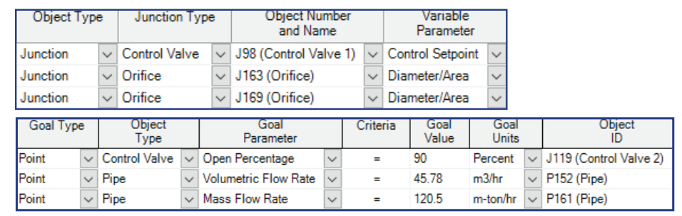
Figure 2: Goal Seek and Control variables and goals used when sizing control valves and orifices according to intended flow.
Energoprojekt Katowice is a leading engineering firm providing design services for conventional power plants, thermal power plants, and heating plants.