Author: Stan Riddle, VibrAlign
Angular misalignment can be confusing to many aligners. Offset, or parallel misalignment, can be pretty straightforward. You can even measure it within a few thousandths of an inch with a good straightedge. But angularity can be just as simple to understand, and measure, if a few things are known.
Basically stated, angularity is the gap difference across two coupling faces-normally top to bottom, or side to side.
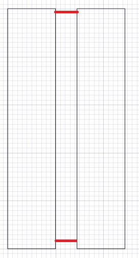
In the first sketch, the two couplings have no angularity. The gap between the top of the coupling faces, and the gap between the bottom of the coupling faces, is zero.
When there is zero angularity, the coupling faces are parallel. It also means the shafts the couplings are mounted to are parallel. They may not be collinear (or in a common straight line), but they are parallel.
In the second sketch, there is a difference in the top gap and the bottom gap. The top gap is 4 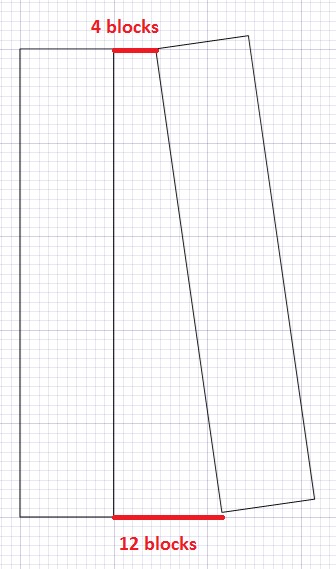 blocks wide. The bottom gap is 12 blocks wide. So the two coupling faces (and the shafts to which they are mounted) are not parallel.
We know that the couplings and shafts should be parallel, but we don’t know how much until we determine two things:
1. How much does each block represent?
2. What is the distance between the top gap and the bottom gap?
Let’s say each horizontal block represents 1 mil (0.001”). If we say 12 mils (bottom gap) minus 4 mils (top gap), we get 8 mils. But that’s only half of what we need to know. We also need to know the distance between the two gaps.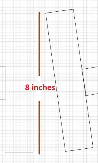
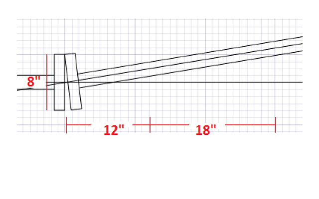
For our example, we measure the diameter of the coupling, which equals 8 inches. Now we have the two measurements we need to define the slope, or angularity, of the coupling faces (and the shafts).
Slope = 8 mils / 8 inches, or 1 mil per inch.
Now we have established the slope – 1 mil per inch. So let’s use this to calculate the correction values at the machine feet.
I need to know the distance from the center of where the two shafts would intersect (normally the center of the coupling), to:
• The inboard feet (12 inches shown here)
• The outboard feet (12 inches + 18 inches, for a total of 30 inches)
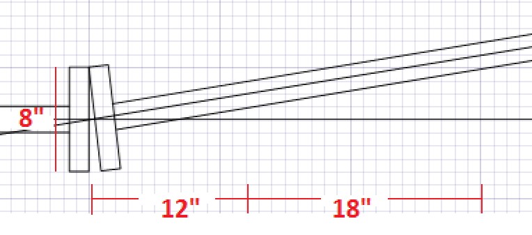
And I need to know the slope per inch, which we already calculated to be 1 mil per inch.
Since the slope of the coupling faces is the same as the slope of the shafts (1 mil/inch)
• Inboard Feet=(1mil/in)(12 inches) = 12 mils
• Outboard Feet-=(1 mil/in)(12 inches + 18 inches) = 30 mils
For more information, contact VibrAlign at (800) 394-3279 or visit www.vibralign.com.