Some older technologies can still bring value to a wide range of applications. So it is with two mechanical devices that are commonly used for soft starting high inertia loads. While both technologies are mature, both can still add value to high performance systems.
The centrifugal clutch and the fluid coupling are older technologies often used in high inertia load systems. Both meet a basic design need: they provide soft engagement of loads while allowing for full or nearly full application of horsepower into drive systems.
As an example, when a bulk conveyor moving mineral ore is started from a standstill there are several dynamics that take place. As the motor begins to accelerate the load, it is operating in a generally inefficient mode. Therefore, current draws during acceleration can be many times higher than normal running current as the motor works to accelerate the load inertia. In some circumstances, motors must be upsized several times over normal running torque levels due to the added current draw needed to accelerate the load.
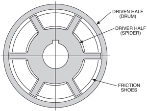
As the interior “spider” hub of a Centrifugal Clutch rotates, centrifugal force causes the shoes with friction facing to expand outward into the driven drum. The greater the rotational speed, the greater the centrifugal force and the greater the transmission of torque via the shoes from input hub to output drum.
There have been estimates made over the years that the motor upsizing may be as high as 6-7 times depending upon how short the acceleration time may be. In one scenario, an application requiring a motor to run at full load amperage of 30 amps for running torque could use a 25 HP motor. For a requirement of six times higher torque that same application will require a 200 HP motor to exceed the 180 amps hurdle at a cost differential of more than 600%! Mechanically, the strain of start-up on drivetrain components can be significant. The excess starting torque needed to accelerate the load can cause stretch on V-belt drives, stress on the shafts/keyway interface in gearboxes and couplings, and more. These additional strains can, over time, cause premature wear and failure of mechanical components, leading to unscheduled and undesirable downtime.
Both the centrifugal clutch and the fluid coupling can be used to mitigate the electrical and mechanical strains during start-up of high inertia systems. Further, they can achieve full or nearly full transmission of motor torque to the drivetrain once they are fully engaged. The two devices provide similar functions but achieve it via different paths.
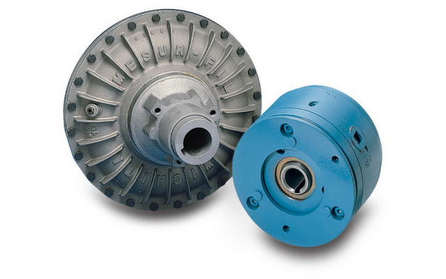
The Centrifugal Clutch works as its name implies. As the interior hub (sometimes called the “spider”) of the unit rotates, centrifugal force causes the shoes with friction facing to expand outward into the driven drum. The greater the rotational speed, the greater the centrifugal force and the greater the transmission of torque via the shoes from input hub to output drum.
In fluid couplings, the function is similar, but the method is different. The fluid coupling is an enclosed system. The input portion goes into a vaned member called the “runner.” The output part is similarly vaned and referred to as the “impeller.” Between the two pieces is a volume of hydraulic fluid. As the runner begins to rotate it starts rotating the fluid. The fluid transfers that rotation to the impeller and from there to the output shaft of the coupling. Like centrifugal clutches, as speed increases so does the torque transfer. Unlike centrifugal clutches, once the unit has achieved maximum speed a fluid coupling will have slippage of 3-5%. Centrifugal clutches have 100% torque transfer when fully engaged.
The impact on motor current of using either device in a mechanical system is to lessen current draw during acceleration. By allowing the motor to accelerate without being loaded, it can rapidly reach its higher operating efficiency without the excessive current draws when operating as a motor alone. This can lower overall current draws to the point where, in many cases, a smaller motor can be used since the excess starting torque (and corresponding current draw) are not needed. In addition to the purchase cost saving of a smaller motor, there are significant power consumption savings.
The softer load engagement can positively impact the mechanical components in the system. Strain on keyways, couplings, belts and gearboxes is reduced, helping to extend the total life of these components.
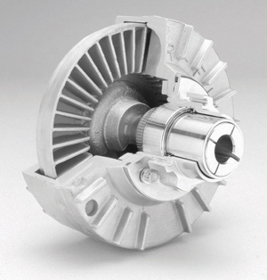
The fluid coupling is an enclosed system. The input portion goes into a vaned member called the “runner.” The output part is similarly vaned and referred to as the “impeller.” Between the two pieces is a volume of hydraulic fluid. As the runner begins to rotate it starts rotating the fluid. The fluid transfers that rotation to the impeller and from there to the output shaft of the coupling. As speed increases so does the torque transfer.
Overload protection is an added benefit of both devices. If the load exceeds the capacity of a centrifugal clutch it can slip. While this will eventually damage the clutch if it occurs for an extended length of time, the clutch can often be easily rebuilt with new friction material shoes. In a fluid coupling the fluid will simply fail to continue to drive. Over an extended period of time this will cause the temperature to rise inside the coupling. An option for the smaller coupling sizes is the inclusion of a ‘fusible plug’ which will melt under excessive temperatures, allowing the fluid to drain from the unit, effectively disabling the coupling. For larger coupling sizes, a sensor can be used to measure input vs. output speeds and shut the motor down if a pre-set differential is exceeded.
As noted earlier, fluid couplings will typically have a 3-5% slip at full engagement compared with no slip for a centrifugal clutch. A second difference is that centrifugal clutches can be designed to engage and operate at lower speeds. Fluid couplings typically require operating speeds of 1200 RPM or higher, while centrifugal clutches can be designed to operate at speeds as low as 400 RPM. On the other end of the speed range, smaller size fluid couplings will work at speeds up to 3500 RPM, less for larger units. Centrifugal clutches can operate at higher speeds if balanced. A stabilizing steel band may be required as speeds exceed certain thresholds.
Another reason why a centrifugal clutch might work better for an application than a fluid coupling is temperature. At ambient temperatures below -10°F, the fluid in a fluid coupling can become excessively viscous. There are special oils that manufacturers can recommend for low temperature applications such as ski lifts and mine conveyors in northern climates. Since centrifugal clutches contain no fluid, this is not a concern.
 Lastly, centrifugal clutches can be used in systems with gas or diesel engines as the input, whereas the fluid couplings cannot. The torque spikes in an engine interrupt the free flow of the hydraulic fluid and reduces the torque transmitting capability of the system.
High inertia loads are common in a wide range of mining equipment, bulk conveying and other industrial processes. Centrifugal clutches or fluid couplings can be used to drop HP requirements for load acceleration as well as to reduce mechanical strain on drive train components. Neither product requires expensive electronic control mechanisms.