True angular misalignment
The common causes of true angular misalignment are when one of the connected shafts is compliantly mounted; for example, when it is located by a self-aligning bearing.
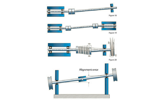
(Fig 18 – A semi-floating shaft located by a self-aligning bearing at one end should be supported with a single-stage coupling at the other)
Alternatively, it could be that an unsupported intermediate shaft is placed between the driver and the load.
(Fig 19 – Two single-stage couplings locate a fully-floating shaft on a stable axis of rotation)
Because the shafts are not mounted conventionally, they will self-align to intersect at the centre of the coupling, which acts as a hinge and, to a degree, a radial bearing. As the coupling is locating the shafts on a stable axis of rotation, it should be of the single-stage type due to the fact that any radial compliance in the coupling is counter-productive.
While couplings based on the flexible shaft can be used in these circumstances, there is a possibility that the coupled system may go into lateral oscillation. This is best described by visualising the effect of a belt and pulley drive mounted on the compliant shaft.
Having a lateral compliance capacity, the coupling responds to fluctuating tension in the belt by allowing lateral oscillation of the shaft.
(Fig 20 – A semi-floating shaft located by a self-aligning bearing at one end and a multi-stage bellows at the other. The coupling reacts to fluctuating tension in the belt by allowing lateral oscillations in the shaft)
The shafts in the first diagram are described as semi-floating, while those in the second are fully-floating. This is an important point as under no circumstances should a coupling with lateral displacement be used with floating shafts. The reason is that this type of coupling has no self-centring action and its use would allow the shafts to orbit in an uncontrolled way.
Couplings capable of overcoming true angular misalignment include the single universal joint with its capacity to handle large offsets, torsional damping, water resistance and lubrication-free operation.
Single-stage disc couplings are also ideal, thanks to their near-infinite life and built-in dynamically balanced properties. Similarly, single-stage bellows with their high torsional stiffness are a good choice in this application.
Zero misalignment
By assembling both shafts in self-aligning bearings, zero misalignment can be achieved. In this way both shafts can float into concentric relationships, allowing the use of a solid coupling which simply supports the shaft in perfect alignment.
(Fig 21 Shafts located by self-aligning bearings can float into perfect alignment for connection with a solid coupling)
Difficulties arise when attempting to connect fixed axis shafts in this way as the level of alignment is difficult to both achieve and maintain, due to settlement, creep, thermal expansion and contraction.
The influence of these factors results in relative movement between the shafts and the alignment achieved in the factory machine may not be achievable ‘in the field’. Therefore a flexible coupling is always the preferred option.
Before installing a solid coupling, an interesting test is to try a flexible coupling first. With the machine at normal operating temperature measure the speed and/or the current drawn by the motor. The difference between these readings and those with the solid coupling indicate the losses generated by the additional friction at the bearings.
Axial compliance
Longitudinal, or axial, shaft displacement can either be intentional or unintentional. The movements due to tolerances, settlement and thermal expansion or contraction cause the latter. While these movements may be small, they can contribute to substantial thrust loads and result in bearing damage.
In these cases a coupling with axial compliance capacity should be selected, predominantly bellows, sliding disc or even helical beam. Multi-stage bellows create the greatest amount of axial compliance while the single-stage disc or bellows provides the smallest.
For intentional shaft displacement, such as on push/pull systems or those with extensible drives where the distance between actuator and load is variable, a teleshaft coupling should be used.
The Huco Dynatork HUCO-POL is a typical example. It comprises precision drawn nesting tubes manufactured from square section brass that can be cut to the appropriate length to provide a wide range of axial movement. This ability to customise the length of the coupling means it can be tailored to required length of stroke.
Another option is the Oldham de-mountable, three part coupling. By mounting the hubs slightly out of full engagement, a limited amount of axial compliance is created.
Torque capacity
Torque is the angular force needed to overcome the resistance of a load. Rotating loads have both a friction and an inertial component and are classified according to whichever dominates. For example, the resistance encountered by a pump delivering fluid is a frictional load as the inertial part is secondary, assuming that the pump runs continuously at a steady speed.
The total application torque comprises the frictional plus inertial elements. If the pump runs at a constant speed, it produces a uniform load and the required power would be given in kW or HP. The kW rating is related to torque by the following formula: torque Nm = kW x 9550 divided by revolutions per minute.
Conversely, a ball-mounted slide table, typified by short cycles of rapid acceleration and deceleration in both directions of rotation will have inertial loads as the predominant factor. These will determine the reversing torque factor of the coupling.
To be more precise, the maximum torque experienced by the coupling may be dictated by whether braking is applied by the load or the motor. In the following diagrams the arrows indicate the direction of the angular forces due to acceleration, deceleration or braking.
Once the maximum torque in the system is known, the selection of the correct coupling can be made by relating it to the peak torque rating. The coupling should be selected using the following formula: peak torque > application torque x service factor.
Torsional stiffness
Torsional stiffness may be expressed in different units but the most common and easiest to work with is Nm/rad. Often described as torque per unit deflection, torsional stiffness is significant in positional system and describes a coupling’s resistance to torsional deflection.
The inverse of torsional stiffness, torsional deflection is defined by deflection per unit torque. This also has many denominations but is best expressed in degrees/Nm.
When used in a closed loop or velocity control system a coupling’s torsional stiffness becomes more critical and forms a contributory factor in calculating the upper limit of dynamic performance and stability. Therefore, the stiffness of a coupling should be such that its torsional resonance frequency exceeds 300 – 600 Hz, depending on dynamics.
Stiffness is at its most critical when load inertia is dominant and becomes less so when the dominance swings in the motor’s favour.


