Authored by William Kruger, Technical & Training Manager, ALL-TEST Pro, LLC, and Alex Panattoni, Control Systems Technician II, City of Henderson Department of Utility Services Electrical Section
Background
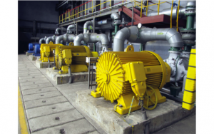
Originally put into operation in 1999, Pump Station P-19A supplies drinking water to the City of Henderson, which is the second largest city in Nevada. Serving a population well over 270,000 people, P-19A is one of the most critical potable pump stations operated by the city. The pump station originally utilized three pumps when its operation began, but in 2006, two more vertical pumps were installed in the pump station (Pumps 1 & 5).
Cause for Concern
In 2006, the pump size was increased, but the motor horsepower remained the same. The motors have a service factor of 1.15 and often exceed 105% of nameplate full-load amperage (FLA). Although this is within the capabilities of the motors, they operate at near maximum output.
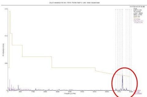
In November 2014, vibration analysis was performed as part of the plant’s Predictive Maintenance Program. While those test results suggested the possibility of early bearing degradation in Motor 5, the rotor bar passing frequency was within range (see Figure 1). The vibration summary concluded that systems were operating within acceptable limits and that no maintenance actions needed to be taken at that time.
Two months later, in January 2015, Motor 5 exhibited signs of overheating; reaching temperatures that exceeded 160-degrees Celsius. While the other pumps did not show any symptoms similar to that of Motor 5, the maintenance team took action and initiated an in-house investigation of all five pump motors using their predictive maintenance equipment.
Comprehensive Testing to Prevent Motor Failure

ALL-TEST PRO 31™ for initial tests
The in-house maintenance team utilized their hand-held ALL-TEST PRO 31™ and ALL-TEST IV PRO™. These high-tech instruments, which are used for de-energized testing, are designed to detect potential winding faults and provide indications of rotor problems. First, they used both the ALL-TEST PRO 31™ and ALL-TEST IV PRO™ to perform winding tests and confirm that the windings were in good condition. Then they used this equipment to conduct ‘insulation to ground’ tests to prove the insulation was not grounded. Next, they performed a rotor inductance test, which measures the inductance of all three phases of a motor at different individual rotor positions. During the test, the rotor is positioned at exact intervals, as seen in the picture to the right.

Rotor Tested at 5-degree Intervals
“We performed an extensive rotor test – taking readings every 5 degrees of shaft rotation using the ALL-TEST IV PRO™ – only then did indications show an issue with both Pump 1 and Pump 5,” explains Alex Panattoni, the Control Systems Technician leading the Electrical Section of the City of Henderson’s Department of Utility Services. “While the tests indicated the possibility of a rotor problem, the results didn’t show the

ALL-TEST IV PRO™ for initial tests
problem definitively. We knew the current was modulating and we put a time trace on it, but we needed to do more extensive testing,” explains Panattoni. At the maintenance team’s request, a third-party specialist went to the pump station to perform vibration analysis. When the vibration analysis did not indicate any electrical faults (pole pass frequency sidebanding) in the associated vibration FFT signatures (see Figure 2), the decision was made to bring in technical support from ALL-TEST Pro to perform additional testing.

Figure 2. January 23, 2015 – Vibration analysis for Motor 5 indicates the presence of low amplitude non-synchronous energy in the PeakVue timedomain data collected on the upper motor bearing. Only recommendations made were to monitor bearings for further degradation. Vibration analysis gave no indication of potential problems with the rotor.

ALL-TEST PRO On-Line II
William Kruger, Technical and Training Manager at ALL-TEST Pro, went to the pump station in January to perform an Electrical Signature Analysis. Electrical Signature Analysis is a diagnostic technology that uses the motors supply voltage and operating current to identify existing and developing faults in the entire motor system. To perform the Electrical Signature Analysis, he brought with him the ALL-TEST PRO On-Line II™. The ATPOL II™ is an energized motor testing tool which, when in ESA mode, evaluates the condition of incoming power, the control circuit, the motor itself, and the driven load. Kruger requested that MVA data be taken simultaneously while the Electrical Signature Analysis was being performed.
Electrical Signature Analysis Reveals Broken Rotor Bars

The RPM values shown in the chart above are consistent with rotor bar anomalies. Motors 1 & 5 indicate an increased “slip frequency”.
During the energized motor tests, data was taken at different times; first shortly after start-up, then again after the pump had been running. Of significance was the large change in rotor speed with a very small change in motor load. The rotor was running considerably below name plate; after running about thirty minutes, the rotor speed was 1171 RPM. This was also confirmed by an independent tach system provided by the third-party who performed the vibration analysis. While the results of the vibration analysis did not show any indications of rotor problems, the speed and the ESA data taken with the ATPOL II™ indicated that several rotor bars were broken (see Figure 3).

Figure 3. January 2015 – Electrical Signature Analysis using the ATPOL II™ – (Before repair) pole pass frequency side bands indicate very severe rotor bar damage; current draw was 820 amps and modulating around16 amps.
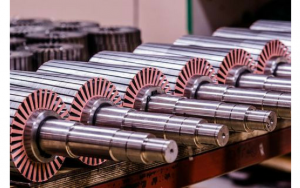
Rotor bars are solid continuous bars that run through the rotor’s steel laminations, which are spaced to allow air flow to cool the rotor. Once the maintenance team received the report from the Electrical Signature Analysis, which showed severe indications of rotor bar issues (Pump 1 had a severity rating of 6 out of 7 and Pump 5 had a severity rating of 7 out of 7), they pulled Motor 5 and found that 30% of the rotor bars were in fact broken.

Rotor bar breaks all occurred in the middle three rows of laminations.

Rebuilding the Rotor with Different Metallurgy
After discussing the issues with the motor manufacturer and a third party motor repair company, the maintenance team chose to have both Motor 1 and Motor 5 rebuilt with copper rotor bars. Pumps 2, 3, and 4 had copper rotor bars and did not have the same issues as Pumps 1 and 5.
The original rotor bars in Pump 1 and Pump 5 had been made of aluminum. This was believed to be the root cause of the problem. Because the motors at P-19A normally run 100% to 110% of load, there is a high current flowing through the rotor. This produces heat that causes expansion and contraction. Over a period of time, the aluminum rotor bar breaks under tension, then the arcing occurs at the spot of the break. The currents are then forced through the remaining bars, putting more loads on them and causing more broken bars, weakening the strength of the entire rotor. This issue would have eventually shorted out the stator winding by the increased operating temperature or arcing metal from the rotor, and would have caused the need for a rewind or possible scrapping of the entire motor, in addition to the repair or replacement of the rotor. Having the motors rebuilt with copper rotor bars enabled the maintenance team to avoid catastrophic failure of their vertical turbine pump motors.

Figure 4. May 5, 2015 – Electrical Signature Analysis using the ATPOL II™ – (After repair) pole pass frequency side bands were gone and current draw was 754 amps with 2 amps modulation
Motor 5 was rebuilt and installed in May of 2015. Another round of MVA and ESA testing was performed immediately after installation to ensure proper operation. The electrical signatures taken in May reported excellent rotor condition (see Figure 4). It also showed that rotor speed increased, while overall current dropped. The newly rebuilt Motor 1 was installed in September 2015 and a third roundof 2015.
Lessons Learned

Chart from third-party vibration analysis performed in May 2015: Rotor bar issues produce low-amplitude sideband sets spaced at “pole passing frequency”. The red circle highlights the location of calculated pole pass frequency sidebands (vertical lines). The absence of these sidebands indicate motor rotor is in good health, as expected with a newly rebuilt rotor.
Having a Predictive Maintenance and proper diagnostic tools program is important. It is essential to equip your maintenance team with state-of-the-art equipment to increase the effectiveness of your Preventive Maintenance program. Tools like the ATPOL II™ exist so you can perform higher level testing, such as Electrical Signature Analysis, which is proving to be a very effective technology for detecting faults before they lead to catastrophic failure.


