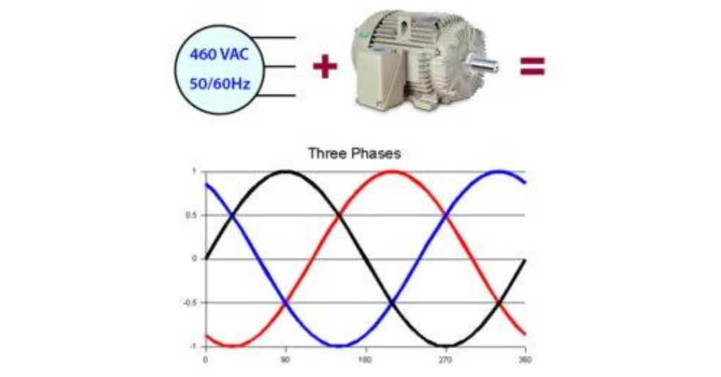
Electric induction motors were designed to be operated on 3-phase sine wave power. This input power is balanced, meaning that the three voltage phases cancel each other out (sum to zero). So when phase A is at +460V, phases B & C will be at -230V. (+460V – 230V – 230V = 0V.) The common mode voltage is the average of the three phases. Since the phases sum to zero, the common mode voltage is also zero when power is properly balanced. When the common mode voltage is zero, the bearings are not usually at risk of electrical bearing damage (except for very large motors, over 500 frame).
But when motors are operated by variable frequency drives (VFDs), the transistors in the drive convert pure sine wave power to a series of positive and negative pulses. Consequently, the input voltage to the motor is never balanced. Instead of each phase voltage being a smooth sine wave, they switch rapidly from positive to zero to negative and back. The phases no longer cancel out, and instead of being zero, the common mode voltage is usually a “square wave” or a “6-step” voltage waveform.
This nonzero common mode voltage in a motor’s stator windings causes motor bearings to “charge up” like a capacitor. For example, suppose that at one moment, the common mode voltage is positive inside the stator windings. This positive common mode voltage induces a positive voltage on the rotor through capacitive coupling. There is also coupling between the windings and the motor frame. But the frame is grounded, so it remains neutral.
With the rotor now positive and the frame still neutral, there is a voltage difference across the motor’s bearings between the rotating shaft and motor’s grounded frame. This voltage across the bearings is usually referred to as shaft voltage. The bearings are full of electrically insulating (dielectric) grease, which forms a non-conductive film between the balls and race walls. So electrical current cannot normally flow through the bearings. This is exactly like a capacitor: two conductors separated by a non-conductive dielectric. If you apply a dc voltage to a capacitor, it will “charge up,” and store energy, but not let appreciable current flow through… unless the dielectric breaks down.
Every capacitor has a breakdown voltage*; a voltage above which the insulator breaks down and allows a burst of current to flow all at once. This is just like lightning: When the voltage between a cloud and the ground gets big enough, the air – normally a good insulator – becomes ionized and suddenly becomes conductive. The result is a rapid discharge: charge flows rapidly through the now-conductive air with the often-destructive release of stored energy. After discharge, the voltage across the capacitor will be zero (or at least much lower).
Now back to the motor: If the shaft voltage builds up high enough, it will discharge by arcing through the bearing: Electrons will leap through the bearing like a miniature lightning bolt, and destructively release the energy that was stored in the bearing’s capacitance. This arc is called a capacitive discharge current, and the damage it does to bearing surfaces is called EDM (electrical discharge machining). Capacitive EDM currents can occur in all motors run on VFDs, regardless of their size.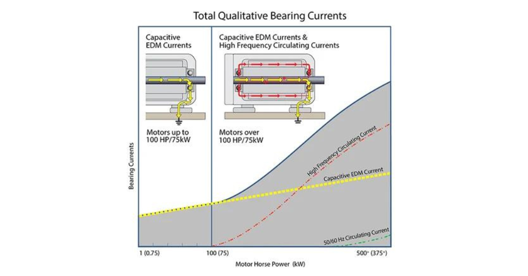 A second form of bearing current produced by VFDs — high frequency (HF) circulating currents — results from a high-frequency magnetic flux produced by common mode current (the sum of the currents flowing in each of the three phases). Just like common mode voltage, common mode current is zero when the power to a motor is balanced, but not when the motor is on a drive. HF circulating current is produced by the imbalanced magnetic flux of the common mode current. Circulating current consists of electrons arcing from the shaft through one bearing, running down the frame, and arcing through the other bearing back to the shaft. The frequency range for these currents is in the kHz or MHz. The size of these currents, and the damage they do, depends on motor size. They first become a problem in motors above 100 HP (75 kW). In general, the larger the motor, the greater the damage they cause.
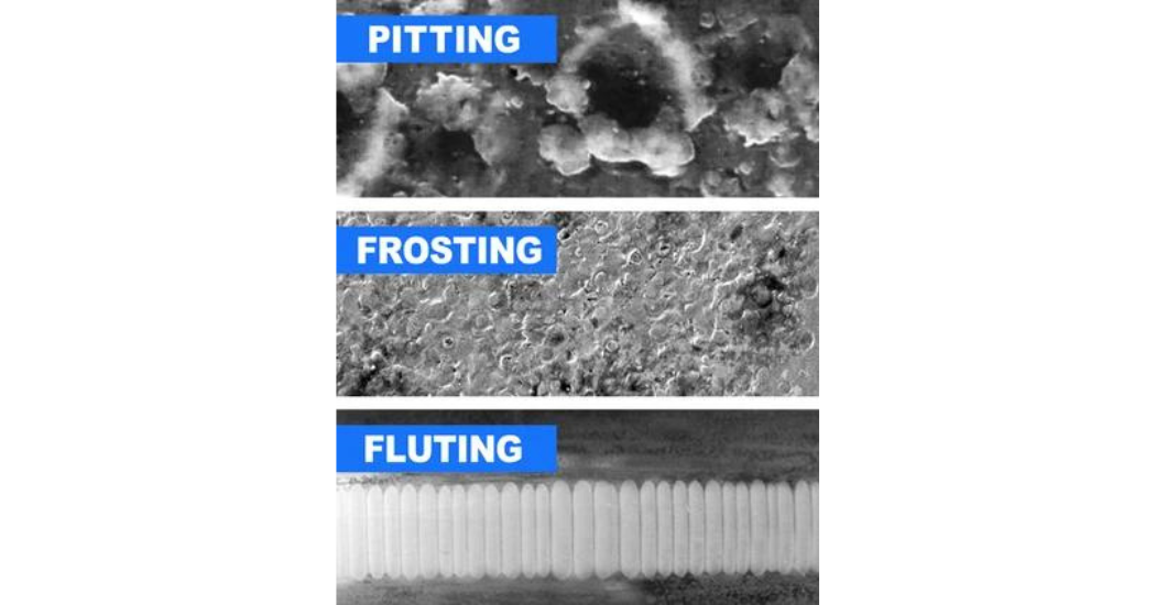
Both capacitive discharge currents and HF circulating currents damage the bearings. Because the bearing lubricant is insulating, these currents can only flow by arcing through the grease. This both degrades the grease and damages the surfaces inside the bearing. This surface damage is directly caused by the electrical arcing through the bearing. Each arc creates a pit, a tiny molten crater where it strikes.
As the pits accumulate, they lead to visible frosting, and eventually to fluting (washboard-like ridges in the bearing race). As bearings degrade, friction increases, leading to noise, further deterioration of the grease, and the likelihood of total bearing failure and costly unplanned downtime. In fact, this entire process can take place in as little as 3 months!
To learn how to prevent this electrical bearing damage from VFDs, read the companion article, Bearing Protection Best Practices
 *For a bearing, the exact breakdown voltage will depend on RPM, temperature, loading, state of lubrication, state of wear, and many other variables. In practice, a bearing’s breakdown voltage is unpredictable, but measured shaft voltages under up to 5V peak (10V peak-peak) are considered safe. Higher shaft voltages are likely to cause discharge.