No matter how matter-of-fact variable frequency drives have become to you, somewhere someone is using one or considering using one for the first time. Think back to when you first thought about applying one of today’s PWM based VFDs to an AC motor. Chances are you probably had a few misconceptions about their abilities and designs. In this article, we will attempt to address a few common myths of VFDs and correct some misconceptions as to their proper usage.
Myth #1: The Output of a VFD is Sinusoidal
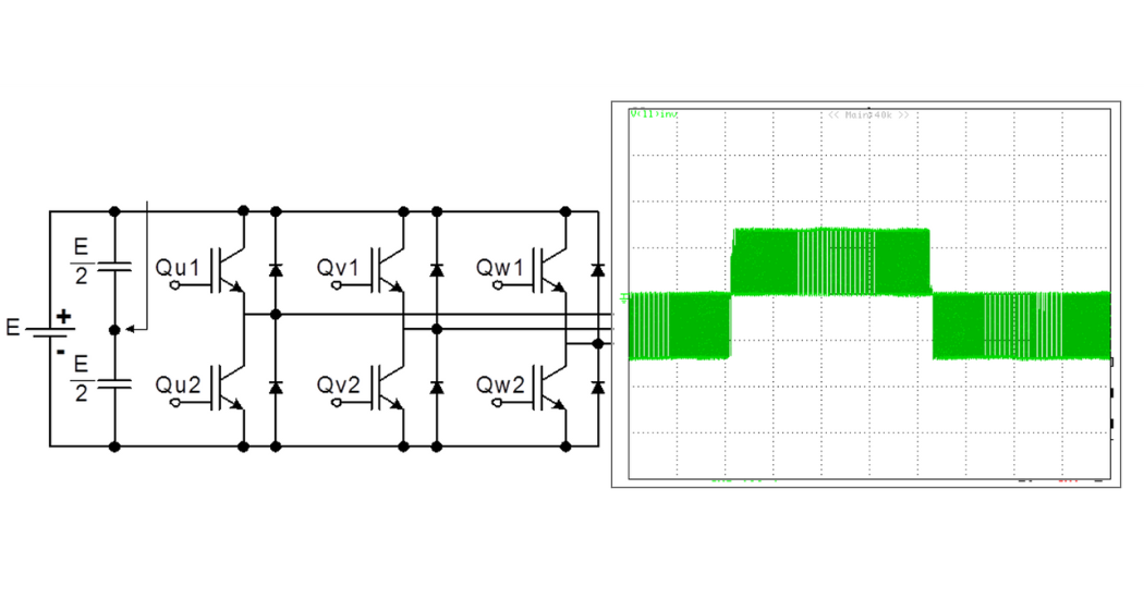
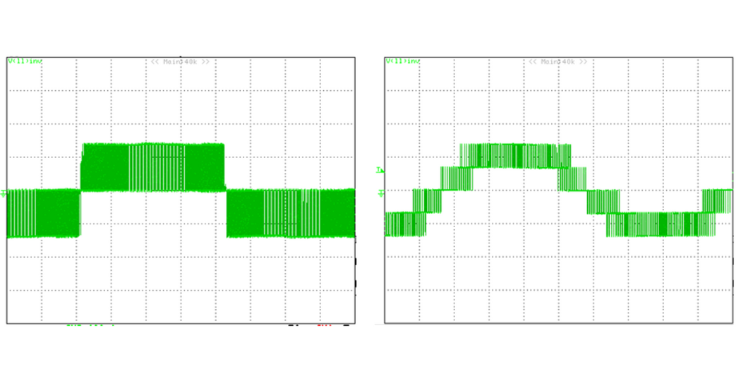
People tend to be more familiar with running their AC induction motors using motor starters. Starting the motor involved connecting the three phase leads of the motor to three phase power. Each phase was a sine wave with frequency of 60Hz and usually had a voltage amplitude of 230volt, 460volt,or 575volt in this part of the world. This applied voltage would create a sine wave current waveform with the same frequency if checked at the motor leads. Thus far, it is quite simple. What happens at the output of a VFD is a different story entirely. A VFD typically rectifies the 3-phase input to a fixed DC voltage which is filtered and stored using large DC bus capacitors. The DC bus voltage is then inverted to yield a variable voltage, variable frequency output. The inversion process is carried out using three pairs of IGBTs, one pair per output phase, as shown below. Since the DC voltage is inverted into AC, the output stage is also called “the inverter”. The duration for which each switch in a given pair is turned ON or held OFF can be controlled and this determines the rms value of the output voltage. The ratio of the output rms voltage to output frequency determines the flux in the AC motor. In general, there is a fixed relationship between the two. When the output frequency increases, the output voltage should also increase at the same rate in order to keep the ratio constant and thus the motor flux constant. Normally the relationship between voltage and frequency is kept linear so that a constant torque can be produced. The resulting voltage waveform applied to the motor winding is shown below. As a side note, sometimes the v/f ratio can be quite nonlinear. This is typically for fan and pump or centrifugal loads which do not require constant torque but instead favor energy savings.
 What makes this work is that as the name implies, an induction motor is a big inductor of sorts. A characteristic of induction is its resistance to changes in current. Whether a current is increasing or decreasing, an inductor will oppose the change. What does this have to do with the PWM voltage waveform seen above? Well instead of letting the current pulse on the same order of the applied voltage pulse, the current will slowly start to rise. Once the pulse has ended the current doesn’t disappear immediately, it slowly starts to ebb away. Generally before it has fallen back to zero, the next pulse comes along and the current starts to slowly rise again, even higher than before because the pulses are getting wider.
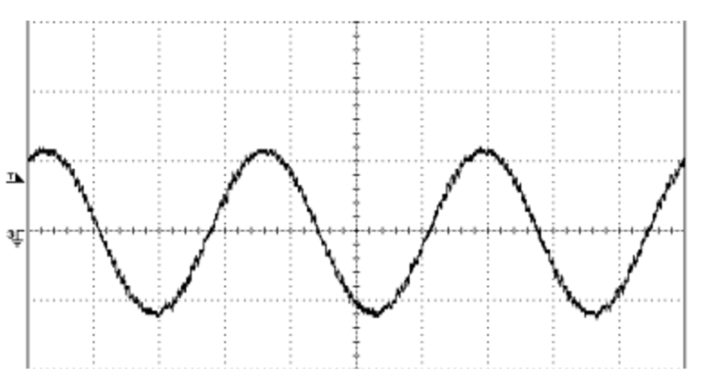 Eventually you get a sinusoidal current waveform albeit with some jagged up and down transitions as the voltage pulses start and end.
So don’t think that you can power your solenoid from a single phase output of a PWM VFD. It’s not that kind of AC voltage.
Myth #2: All VFDs are the Same
The common AC Variable Frequency Drive of today is a fairly mature product. Most commercially available drives contain the same basic components: a bridge rectifier, a soft charging circuit, a DC Bus capacitor bank, and an output inverter section. Granted, there are differences in how the inverter section does its switching and there are differences in how reliable the components are or how efficient the thermal dissipation scheme is but the basic components remain the same.
There are exceptions to this “All The Same” thinking. For instance, some VFDs offer a Three Level output section. This output section allows the output pulses to vary from half bus voltage level pulses and full bus level pulses. Contrast the three-level output pulses to the two level output pulses shown next to it.
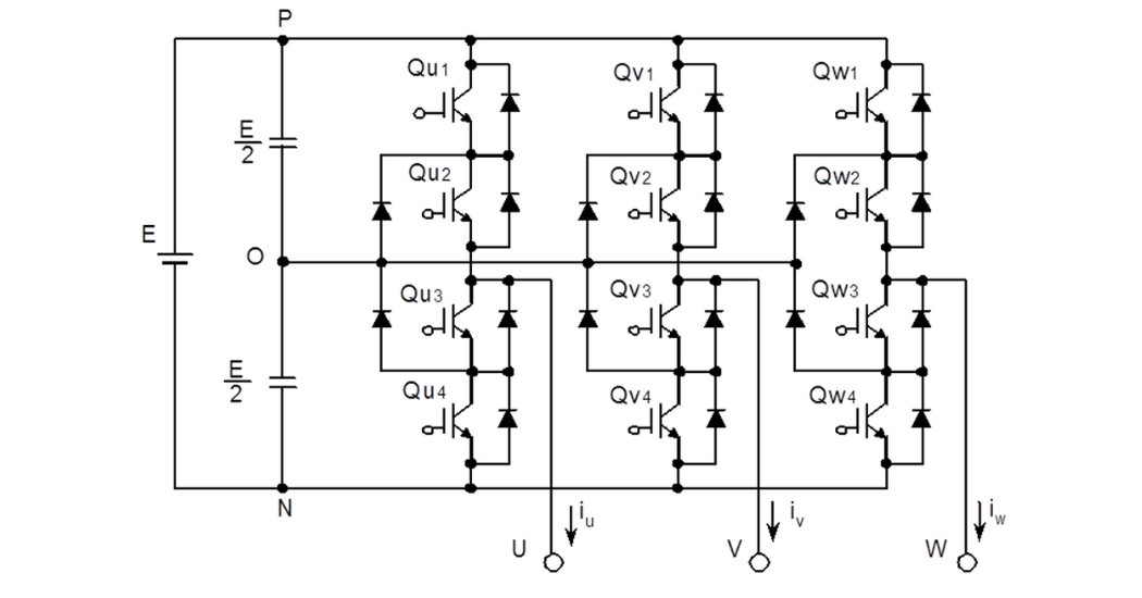
 In order to achieve the three-level output, the output section has to have twice the number of output switches plus clamping diodes as shown below. The benefit gained by using a three-level output is reduction in voltage amplification at the motor due to reflected wave, lower common mode voltage, shaft voltage, and bearing current.
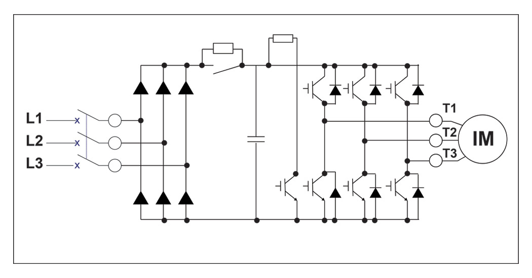
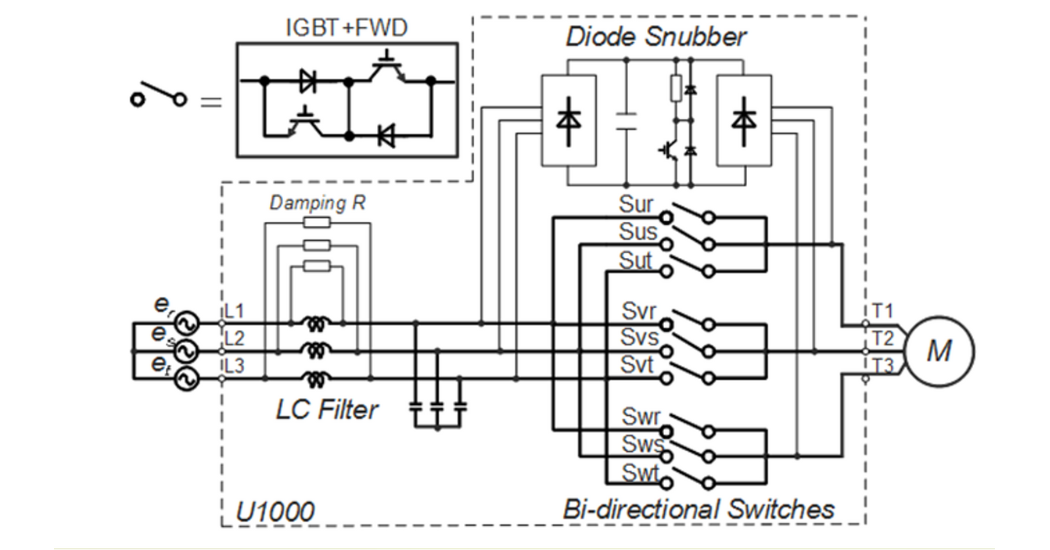
 Maybe an even more atypical type of VFD is the matrix style inverter. These VFDs feature no DC bus or bridge rectifier. Instead the VFD uses bi-directional switches that can connect any of the incoming phase voltages to any of the three output phases. The upside of this arrangement is that power is allowed to flow freely from line to motor or motor to line for fully regenerative four quadrant operation! The downside is that there is filtering required on the input to the drive since extra inductance is necessary to filter the PWM waveform so that it does not affect the input AC lines.
 These are two examples and there are more that prove that not all AC VFDs are the same.
Myth #3: VFDs Cure your Power Factor Issues
It is not uncommon to see VFD manufacturers quote power factor statistics like “0.98 displacement power factor” or “near unity power factor”. And it is true that the input displacement power factor improves once a VFD is installed in front of an induction motor. The VFD uses its internal capacitor bus to supply any reactive current that the motor requires, thereby protecting the AC Line for being the source of the reactive current and thus lowering the displacement power factor. However, displacement power factor is not the full story.
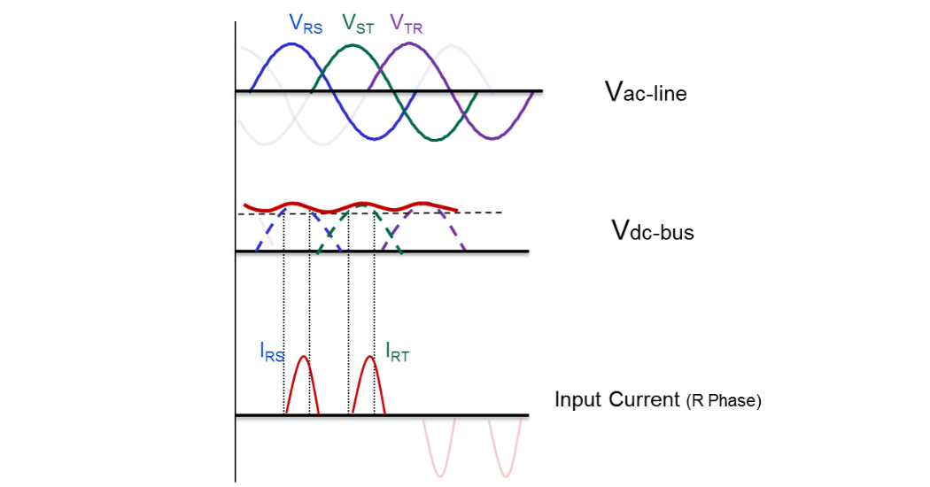
The full story of the power factor calculation is that it must include the reactive power that is demanded by harmonics created when AC voltage is rectified to DC. The diode bridge conducts the current from the AC Line to the DC Bus in a discontinuous way. It is important to remember that a diode will conduct only when the voltage on the anode side is higher than the voltage on the cathode side. This means that the diodes are only “ON” at the peak of each phase during both the positive and negative portion of the sine wave. This leads to a ripple-like voltage waveform and it also causes the input current to be distorted and discontinuous as shown below.
 Much can be said about harmonics regarding how to calculate them and how to mitigate them but either way, to get true power factor you must include their effects. The formula below helps to get a handle on their influence over true power factor. In the formula, THD stands for Total Harmonic Distortion.
TruePowerFactor≈DisplacementPowerFactor√1+THD2
For the discontinuous input current shown above the THD would be in the neighborhood of 100% or more. Substituting that into the equation yields a True Power Factor closer to 0.71 compared to a displacement power factor of 0.98, which disregards harmonics.
Not to panic though, there are currently many ways to reduce the THD. These techniques make use of passive and active methods of making the input current waveform much less distorted and the THD much lower. The aforementioned matrix VFD is an example of an active method of THD reduction.
Myth #4: You Can Run a Motor at any Speed with a VFD
The beauty of using VFDs is that they can vary both their output voltage and output frequency. Their ability to run the motor slower and faster than its nameplate rated speed is part of why they get specified so often. Take the motor out of the equation and this myth is actually true. Without the limitations of the motor, the VFD can easily run any frequency within it speed range without limitation. But the reality of it is that the motor is necessary to do real work and its cooling and power needs start to limit the actual speed range of the motor/drive combination.
- Limit #1: From a motor cooling point of view, turning some motors too slowly is not a good idea. In particular, totally enclosed fan cooled motors have limitations because the fan that blows air over the motor shell is attached to the motor shaft. The slower the motor is operated the lower the CFM cooling the motor. Most motor manufacturers specify speed ranges for their motor designs that will reflect how slow the motor can be run, especially while loaded. TEFC motors typically are not recommended for operation at full load below 15 Hz (a 4:1 speed range).
- Limit #2: It is not always stated on the motor nameplate but mechanically motors have a limitation to their speed range. Referred to, commonly, as the Maximum Safe Operating Speed, this speed is tied to mechanical limitations such as bearings and balance. Some motor datasheets will specify the maximum speed.
- Limit #3: Before the motor reaches its maximum operating speed, the motor could run out of torque. This speed limitation is not one of cooling or mechanics, but is due to power limitation, which is a product of speed and torque. To be exact, the VFD runs out of voltage. It is important to mention here that the rotation of the motor also generates a voltage of its own, referred toas back emf, which increases with speed. The back emf is being produced by the motor to oppose the supplied voltage from the VFD. At higher speeds, the VFD has to supply more voltage to overcome the back emf so that current can still flow into the motor since current is instrumental in producing torque. After a certain point, the VFD cannot push any more current into the motor because the output voltage has reached maximum and so the motor torque reduces, which in turn reduces speed. The reduction in speed results in lower back emf which in turn allows more current to flow into the motor again. There is an equilibrium point where the motor reaches the maximum speed for a given torque condition so that the product of torque and speed equals its power capability.
Let’s take a step back. VFDs can produce constant torque from a motor by keeping the V/f (voltage by frequency ratio or V by f ratio) constant, as shown below.
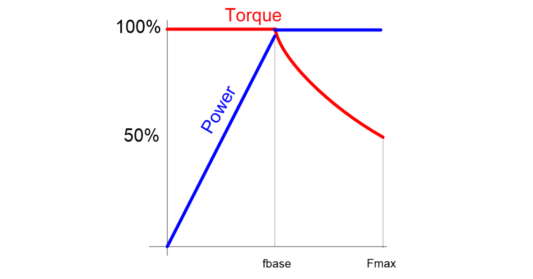
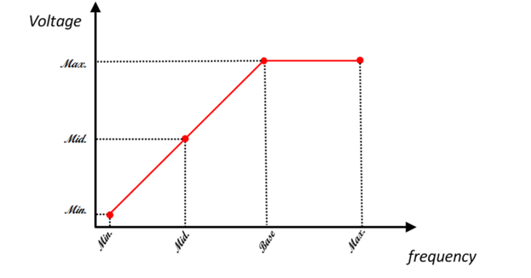 When the output frequency is increased, the voltage increases linearly. The problem arises when the frequency is raised beyond the base frequency of the motor, most commonly 60Hz in this part of the world. Beyond the base frequency, the output voltage cannot increase thereby resulting in the ratio of voltage to frequency to reduce. The ratio of voltage to frequency is a measure of the magnetic field strength in the motor and reducing it reduces the torque capability of the motor. Hence, the ability to have the motor produce rated torque at higher than base speed must decline at a rate of 1/frequency, so that the product of torque and speed, which equals power, is constant. The region of operation above base speed is called the constant power range, while operation at speeds below the base speed is called the constant torque range.
 Myth #5: A VFD’s Input Current Should be Higher than its Output Current
So maybe this is not a myth but a misunderstanding. Some VFD users check their output current and input current with a current clamp or using VFD display monitors and find that the input current is much lower than their output current. It doesn’t seem to align with the idea that the VFD should have some losses due to its own thermal component losses so input should always be slightly higher that output. The concept is correct but it is power not current that should be considered.
P¿≅Pout
V¿∙I¿≅Vout∙Iout
The voltage portion of the power equation is pretty straightforward. The input voltage is always at the AC Line voltage. The output voltage varies with the speed per the V/f pattern. The current components of the equation are a little bit more complex. The key to current components is to understand that atypical induction motor has two current components. One is responsible for producing the magnetic field in the motor which is necessary to rotate the motor while the second component is the torque producing current, which as the name suggests, is responsible for producing torque. The drive consumes input current proportional to the motor’s active torque demand, or load. The current needed for producing the magnetic field typically does not vary with speed and is provided by the drive’s main DC bus capacitors, which are charged up during power up. Under low torque conditions, the output current may seem to be much higher than the input current since the input current mirrors only the torque producing current plus some harmonics but does not include the magnetizing current. The magnetizing current circulates in between the DC bus capacitors and the motor. Even at full load conditions, the input current will typically be lower than the motor current since the input still does not have any magnetizing current component in it.
To summarize this concept we can remember we are balancing input and output power. A good example is to consider a motor that is fully loaded but at a low speed. The input voltage is at the rated line while the output voltage will be low due to the low speed. Because of the full load on the motor,output current will be high. In order to balance the power equation the input current has to be lower than the output current! And now we know how and why that is possible.
Learn more about Yaskawa’s VFDs.